How to Use MAXREFDES117: Examples, Pinouts, and Specs
Introduction
The MAXREFDES117 is a high-efficiency, low-noise power supply reference design that integrates a DC-DC converter and supporting components. It is engineered to deliver a stable output voltage with minimal ripple, making it ideal for powering sensitive electronic devices such as sensors, microcontrollers, and communication modules. Its compact design and robust performance make it a popular choice for applications requiring reliable and efficient power delivery.
Explore Projects Built with MAXREFDES117


Explore Projects Built with MAXREFDES117
Common Applications and Use Cases
- Wearable devices
- Medical sensors
- IoT devices
- Portable electronics
- Low-power microcontroller systems
Technical Specifications
Key Technical Details
- Input Voltage Range: 1.8V to 5.5V
- Output Voltage: Configurable, typically 1.8V or 3.3V
- Output Current: Up to 100mA
- Efficiency: Up to 95% (depending on load and input voltage)
- Ripple Voltage: < 10mV (typical)
- Operating Temperature Range: -40°C to +85°C
- Form Factor: Compact PCB design (dimensions vary by implementation)
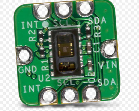
Pin Configuration and Descriptions
The MAXREFDES117 module typically includes the following pins:
| Pin Name | Type | Description |
|---|---|---|
| VIN | Power Input | Input voltage pin. Accepts 1.8V to 5.5V. |
| GND | Ground | Ground connection for the circuit. |
| VOUT | Power Output | Regulated output voltage pin. Provides a stable voltage (e.g., 1.8V or 3.3V). |
| EN | Enable Input | Active-high enable pin. Enables the output when pulled high. |
| FB | Feedback Input | Voltage feedback pin for output regulation. |
| NC | No Connection | Not connected internally. Leave unconnected or use as needed in the design. |
Usage Instructions
How to Use the MAXREFDES117 in a Circuit
- Power Input: Connect the VIN pin to a DC power source within the specified input voltage range (1.8V to 5.5V). Ensure the power source can supply sufficient current for your application.
- Output Voltage Configuration: The output voltage is typically set using an external resistor divider connected to the FB pin. Refer to the datasheet for resistor value calculations.
- Enable Pin: Pull the EN pin high to enable the output. If unused, connect it to VIN to keep the module always enabled.
- Output Connection: Connect the VOUT pin to the load. Ensure the load does not exceed the maximum output current (100mA).
- Bypass Capacitors: Place appropriate bypass capacitors (e.g., 10µF ceramic capacitors) close to the VIN and VOUT pins to minimize noise and ripple.
Important Considerations and Best Practices
- Thermal Management: Ensure adequate ventilation or heat dissipation if operating at high loads or in warm environments.
- Input Voltage: Avoid exceeding the maximum input voltage (5.5V) to prevent damage to the module.
- Output Ripple: Use low-ESR capacitors on the output to minimize ripple voltage.
- PCB Layout: Follow good PCB design practices, such as keeping traces short and using a solid ground plane, to reduce noise and improve stability.
Example: Using MAXREFDES117 with Arduino UNO
The MAXREFDES117 can be used to power an Arduino UNO or other microcontroller boards. Below is an example of how to connect the module and enable it:
Circuit Connection
- Connect the VIN pin of the MAXREFDES117 to a 5V power source.
- Connect the GND pin to the Arduino's GND.
- Connect the VOUT pin to the Arduino's 3.3V input (if the module is configured for 3.3V output).
- Pull the EN pin high to enable the module.
Arduino Code Example
The following code demonstrates how to monitor the output voltage of the MAXREFDES117 using an analog input pin on the Arduino UNO:
// Define the analog pin connected to the MAXREFDES117 VOUT
const int voutPin = A0;

// Define the reference voltage of the Arduino (5V for UNO)
const float referenceVoltage = 5.0;

// Define the ADC resolution (10-bit for Arduino UNO)
const int adcResolution = 1024;

void setup() {
  // Initialize serial communication for debugging
  Serial.begin(9600);
}

void loop() {
  // Read the analog value from the VOUT pin
  int analogValue = analogRead(voutPin);

  // Convert the analog value to a voltage
  float outputVoltage = (analogValue * referenceVoltage) / adcResolution;

  // Print the output voltage to the serial monitor
  Serial.print("Output Voltage: ");
  Serial.print(outputVoltage);
  Serial.println(" V");

  // Wait for 1 second before the next reading
  delay(1000);
}
Notes:
- Ensure the MAXREFDES117 is configured to output a voltage compatible with the Arduino's input voltage range.
- Use a multimeter to verify the output voltage before connecting it to the Arduino.
Troubleshooting and FAQs
Common Issues and Solutions
| Issue | Possible Cause | Solution |
|---|---|---|
| No output voltage | EN pin is not pulled high | Ensure the EN pin is connected to VIN or a high logic level. |
| Output voltage is unstable or noisy | Insufficient bypass capacitors | Add low-ESR capacitors close to the VIN and VOUT pins. |
| Output voltage is incorrect | Incorrect resistor divider values on FB pin | Verify and recalculate the resistor values for the desired output voltage. |
| Module overheats | Excessive load current or poor ventilation | Reduce the load or improve thermal management (e.g., add a heatsink). |
| No power to the module | Input voltage is out of range | Ensure the input voltage is within the 1.8V to 5.5V range. |
FAQs
Can the MAXREFDES117 power a 5V device?
- No, the module is typically configured for 1.8V or 3.3V output. It cannot directly provide 5V output.
What is the maximum load current?
- The module can supply up to 100mA of current. Exceeding this limit may cause instability or damage.
Can I use the MAXREFDES117 with a battery?
- Yes, as long as the battery voltage is within the 1.8V to 5.5V input range.
How do I reduce output ripple?
- Use low-ESR capacitors on the output and ensure proper PCB layout to minimize noise.
By following this documentation, users can effectively integrate the MAXREFDES117 into their designs and troubleshoot common issues.