How to Use Motor Controller: Examples, Pinouts, and Specs
Introduction
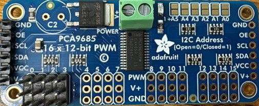
The Adafruit P815C Motor Controller is a versatile device designed to regulate the speed, position, and direction of motors by controlling the power supplied to them. This component is essential for applications requiring precise motor control, such as robotics, automation systems, and electric vehicles. Its compact design and robust functionality make it suitable for both hobbyist projects and industrial applications.
Explore Projects Built with Motor Controller

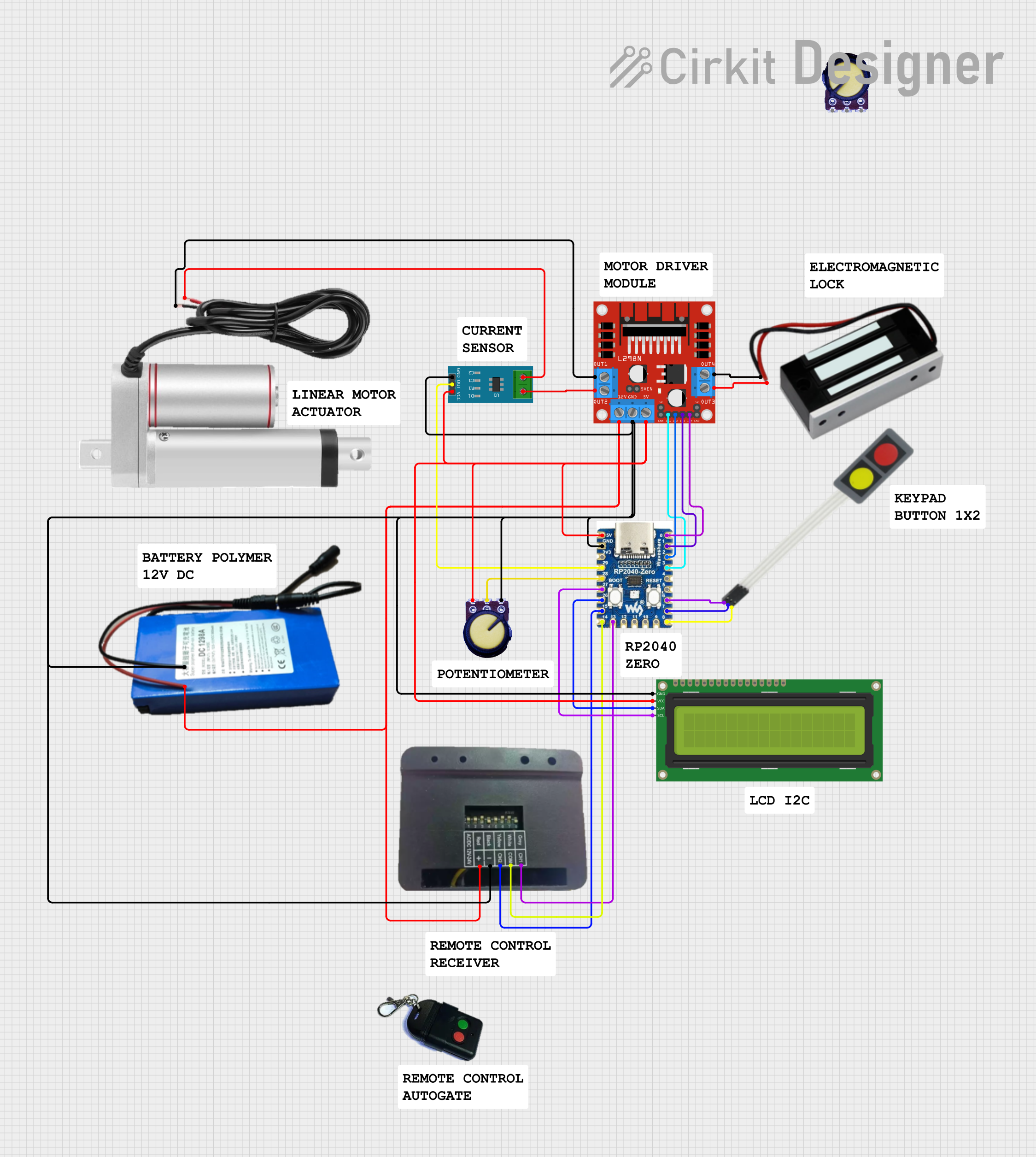
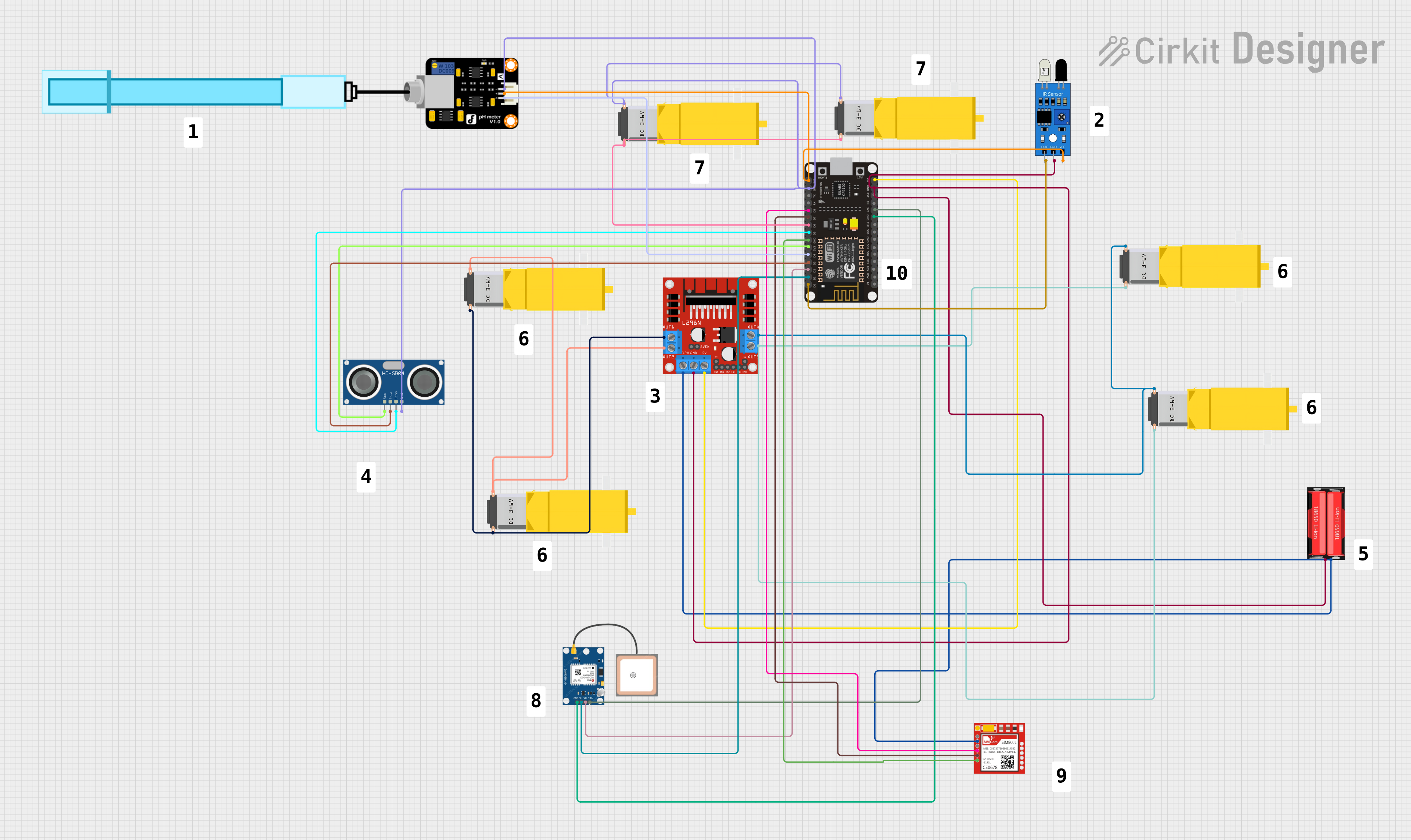
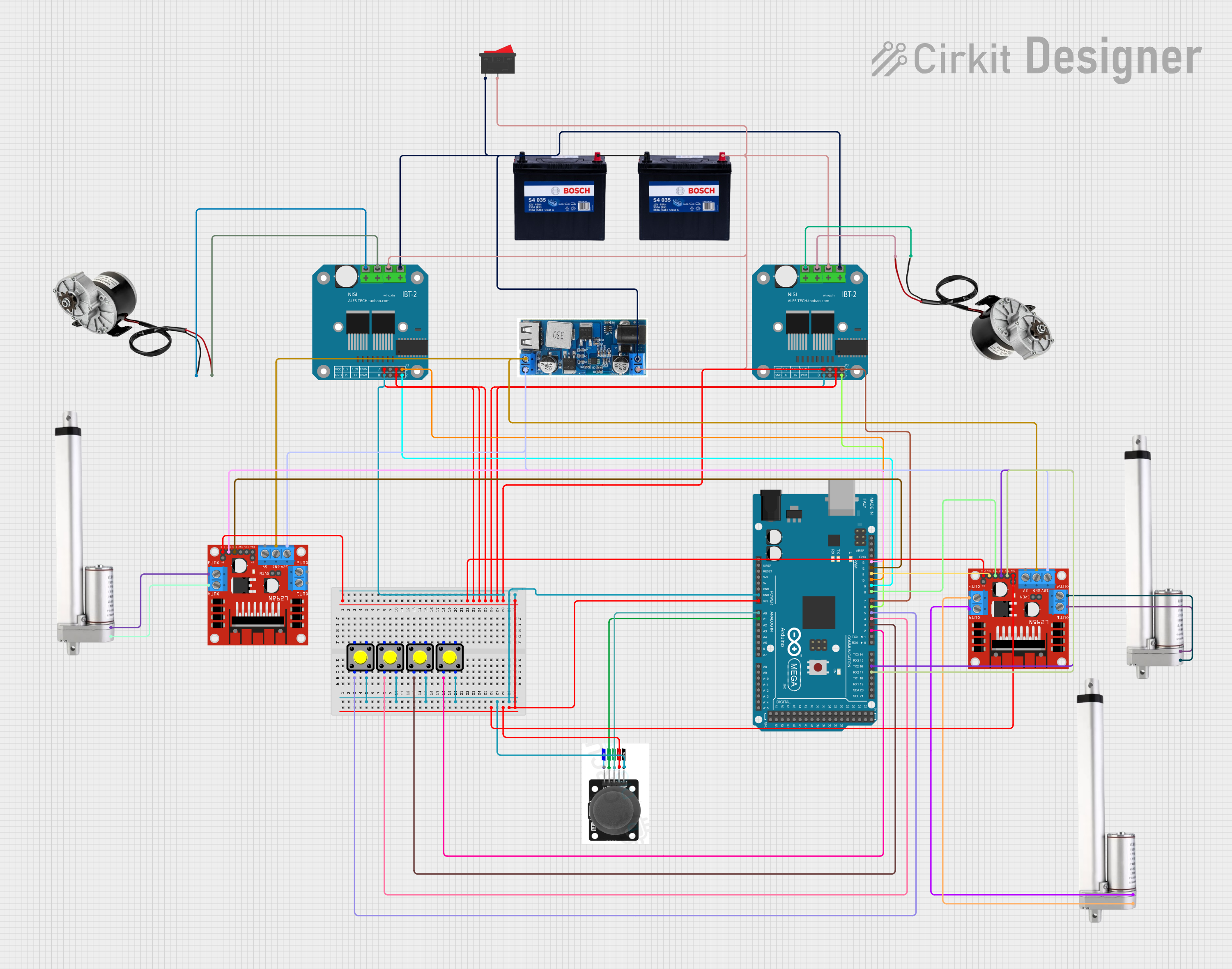
Explore Projects Built with Motor Controller
Common Applications and Use Cases
- Robotics: Controlling the movement of robotic arms or mobile robots.
- Automation: Managing conveyor belts, pumps, or other automated systems.
- Electric Vehicles: Regulating motor speed and direction in small electric vehicles.
- DIY Projects: Building motorized gadgets or custom machinery.
Technical Specifications
The Adafruit P815C Motor Controller is designed to handle a wide range of motors and offers the following key specifications:
| Parameter | Value |
|---|---|
| Input Voltage Range | 6V to 24V |
| Maximum Current Output | 5A continuous, 10A peak |
| Control Interface | PWM (Pulse Width Modulation) |
| Operating Temperature | -20°C to 85°C |
| Dimensions | 50mm x 40mm x 15mm |
| Weight | 25g |
Pin Configuration and Descriptions
The P815C Motor Controller features a simple pinout for easy integration into your circuit:
| Pin Name | Pin Type | Description |
|---|---|---|
| VIN | Power Input | Connect to the positive terminal of the power supply (6V to 24V). |
| GND | Power Ground | Connect to the ground terminal of the power supply. |
| M+ | Motor Output | Connect to the positive terminal of the motor. |
| M- | Motor Output | Connect to the negative terminal of the motor. |
| PWM | Control Input | Accepts a PWM signal (0-100% duty cycle) to control motor speed. |
| DIR | Control Input | Logic input to set motor direction (HIGH for forward, LOW for reverse). |
| EN | Control Input | Enable pin; set HIGH to enable the motor controller, LOW to disable it. |
Usage Instructions
How to Use the Component in a Circuit
- Power Supply: Connect the VIN and GND pins to a power source within the specified voltage range (6V to 24V).
- Motor Connection: Attach the motor terminals to the M+ and M- pins, ensuring correct polarity.
- Control Signals:
- Use a microcontroller (e.g., Arduino UNO) to generate PWM signals for the PWM pin.
- Set the DIR pin HIGH or LOW to control the motor's direction.
- Use the EN pin to enable or disable the motor controller.
Important Considerations and Best Practices
- Current Rating: Ensure the motor's current draw does not exceed the controller's maximum current rating (5A continuous, 10A peak).
- Heat Dissipation: For high-current applications, consider adding a heat sink or active cooling to prevent overheating.
- PWM Frequency: Use a PWM frequency between 1kHz and 20kHz for optimal performance.
- Power Supply: Use a stable and adequately rated power supply to avoid voltage drops or surges.
Example Code for Arduino UNO
Below is an example of how to control the Adafruit P815C Motor Controller using an Arduino UNO:
// Define pin connections
const int pwmPin = 9;  // PWM signal pin connected to the motor controller
const int dirPin = 8;  // Direction control pin
const int enPin = 7;   // Enable pin

void setup() {
  // Set pin modes
  pinMode(pwmPin, OUTPUT);
  pinMode(dirPin, OUTPUT);
  pinMode(enPin, OUTPUT);

  // Initialize motor controller
  digitalWrite(enPin, HIGH);  // Enable the motor controller
  digitalWrite(dirPin, HIGH); // Set initial direction to forward
}

void loop() {
  // Gradually increase motor speed
  for (int speed = 0; speed <= 255; speed++) {
    analogWrite(pwmPin, speed); // Set motor speed (0-255)
    delay(20);                  // Wait 20ms before increasing speed
  }

  delay(1000); // Run at full speed for 1 second

  // Gradually decrease motor speed
  for (int speed = 255; speed >= 0; speed--) {
    analogWrite(pwmPin, speed); // Decrease motor speed
    delay(20);                  // Wait 20ms before decreasing speed
  }

  delay(1000); // Pause for 1 second before reversing direction

  // Reverse motor direction
  digitalWrite(dirPin, LOW); // Set direction to reverse
}
Troubleshooting and FAQs
Common Issues and Solutions
Motor Not Running:
- Ensure the EN pin is set HIGH to enable the motor controller.
- Verify that the power supply voltage is within the specified range (6V to 24V).
- Check the motor connections to the M+ and M- pins.
Motor Running in the Wrong Direction:
- Reverse the logic level on the DIR pin (HIGH for forward, LOW for reverse).
- Double-check the motor's wiring to ensure correct polarity.
Overheating:
- Ensure the motor's current draw does not exceed the controller's maximum rating.
- Add a heat sink or active cooling if the controller operates at high currents for extended periods.
PWM Signal Not Working:
- Verify that the PWM signal is within the recommended frequency range (1kHz to 20kHz).
- Check the microcontroller's PWM pin configuration and ensure it is functioning correctly.
FAQs
Q: Can I use this motor controller with a 3.3V microcontroller?
A: Yes, the control pins (PWM, DIR, EN) are compatible with 3.3V and 5V logic levels.
Q: What type of motors can this controller drive?
A: The P815C is designed for brushed DC motors. It is not suitable for stepper motors or brushless DC motors.
Q: Is reverse polarity protection included?
A: No, the P815C does not have built-in reverse polarity protection. Ensure correct wiring to avoid damage.
Q: Can I control multiple motors with one controller?
A: No, the P815C is designed to control a single motor. For multiple motors, use additional controllers.