How to Use IR Phototransistor: Examples, Pinouts, and Specs
Introduction
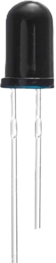
An IR phototransistor is a semiconductor device designed to detect infrared (IR) light and convert it into an electrical signal. It operates similarly to a regular phototransistor but is specifically sensitive to IR wavelengths. When exposed to IR light, the phototransistor allows current to flow, which can be measured or used to trigger other components in a circuit.
Explore Projects Built with IR Phototransistor
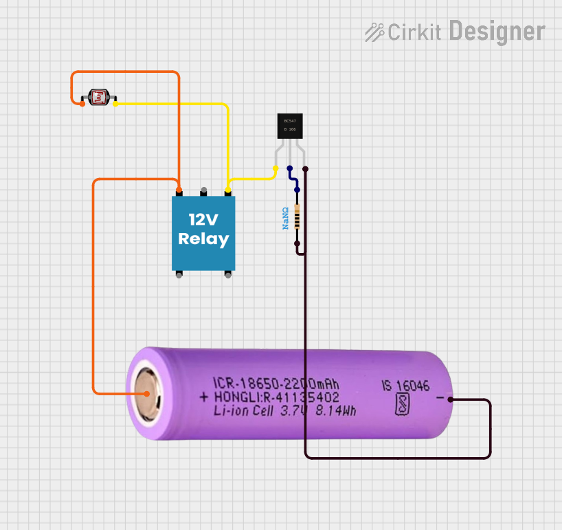
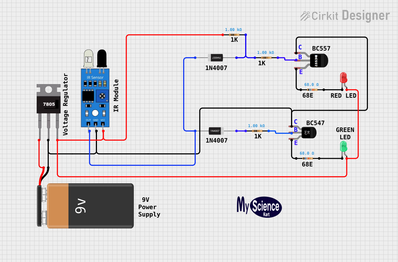
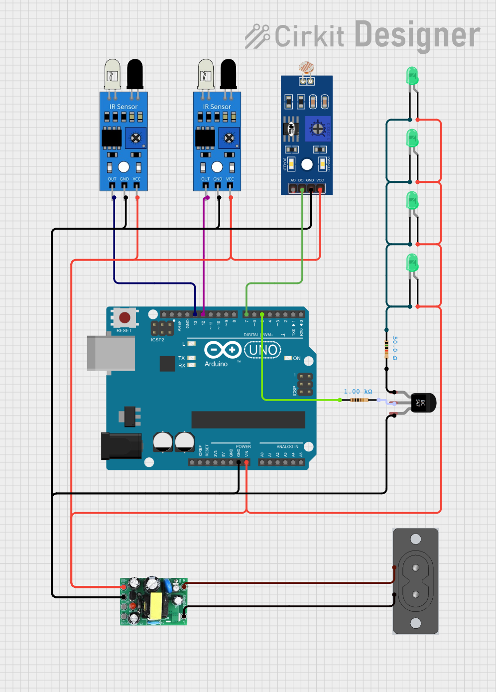
Explore Projects Built with IR Phototransistor
Common Applications and Use Cases
- Remote control systems (e.g., TVs, air conditioners)
- Optical communication systems
- Proximity sensors
- Line-following robots
- IR beam break detection systems
- Flame detection in safety systems
Technical Specifications
Below are the general technical specifications for a typical IR phototransistor. Note that exact values may vary depending on the specific model.
| Parameter | Value |
|---|---|
| Wavelength Sensitivity | 850 nm to 950 nm (typical) |
| Collector-Emitter Voltage | 30V (maximum) |
| Emitter-Collector Voltage | 5V (maximum) |
| Collector Current (Ic) | 20 mA (maximum) |
| Power Dissipation | 150 mW (maximum) |
| Response Time | 10 µs to 50 µs (typical) |
| Operating Temperature Range | -40°C to +85°C |
Pin Configuration and Descriptions
IR phototransistors typically have two pins: the collector and the emitter. Some models may include a base pin for additional control, but this is less common.
| Pin | Name | Description |
|---|---|---|
| 1 | Collector | The pin where the current flows in when IR light is detected. |
| 2 | Emitter | The pin where the current exits the phototransistor. |
Note: Ensure correct polarity when connecting the phototransistor to a circuit. Reversing the pins may damage the component or result in improper operation.
Usage Instructions
How to Use the Component in a Circuit
Basic Circuit Setup:
- Connect the collector pin to the positive voltage supply (via a pull-up resistor, typically 10 kΩ).
- Connect the emitter pin to ground.
- When IR light is detected, the phototransistor conducts, allowing current to flow from the collector to the emitter. This creates a voltage drop across the pull-up resistor, which can be measured as an output signal.
Interfacing with a Microcontroller (e.g., Arduino UNO):
- Connect the collector pin to a digital input pin on the Arduino through a pull-up resistor.
- Connect the emitter pin to the Arduino's ground (GND).
- Use the Arduino to read the digital signal and respond to IR light detection.
Example Arduino Code
Below is an example of how to use an IR phototransistor with an Arduino UNO to detect IR light:
// Define the pin connected to the phototransistor's collector
const int phototransistorPin = 2; // Digital pin 2

void setup() {
  pinMode(phototransistorPin, INPUT); // Set the pin as an input
  Serial.begin(9600); // Initialize serial communication for debugging
}

void loop() {
  int sensorValue = digitalRead(phototransistorPin); // Read the phototransistor state

  if (sensorValue == LOW) {
    // LOW indicates IR light is detected (current flows through the phototransistor)
    Serial.println("IR light detected!");
  } else {
    // HIGH indicates no IR light is detected
    Serial.println("No IR light detected.");
  }

  delay(500); // Wait for 500ms before the next reading
}
Important Considerations and Best Practices
- Ambient Light Interference: IR phototransistors can be affected by ambient IR sources (e.g., sunlight, incandescent bulbs). Use an IR filter or modulated IR signals to improve accuracy.
- Pull-Up Resistor: The value of the pull-up resistor affects the sensitivity and response time. Experiment with different resistor values (e.g., 1 kΩ to 100 kΩ) to suit your application.
- Distance and Angle: The sensitivity of the phototransistor decreases with distance and angle from the IR source. Ensure proper alignment for optimal performance.
- Power Dissipation: Avoid exceeding the maximum power dissipation rating to prevent damage to the component.
Troubleshooting and FAQs
Common Issues and Solutions
No Response to IR Light:
- Cause: Incorrect wiring or reversed polarity.
- Solution: Double-check the pin connections and ensure the collector is connected to the positive voltage supply.
False Triggers in Bright Environments:
- Cause: Ambient IR interference.
- Solution: Use an IR filter or modulate the IR source to distinguish it from ambient light.
Slow Response Time:
- Cause: High pull-up resistor value.
- Solution: Reduce the pull-up resistor value to increase the response speed.
Overheating or Damage:
- Cause: Exceeding voltage, current, or power ratings.
- Solution: Ensure the component operates within its specified limits.
FAQs
Q: Can I use an IR phototransistor to detect visible light?
A: No, IR phototransistors are specifically designed to detect infrared light. For visible light detection, use a standard phototransistor or a photodiode.
Q: How do I increase the detection range of an IR phototransistor?
A: Use a more powerful IR emitter, ensure proper alignment, and minimize ambient light interference.
Q: Can I connect the phototransistor directly to an analog input pin?
A: Yes, you can connect it to an analog pin to measure varying light intensities. However, you may need to adjust the circuit design (e.g., use a smaller pull-up resistor).
Q: What is the difference between an IR phototransistor and an IR photodiode?
A: An IR phototransistor amplifies the current generated by IR light, while an IR photodiode generates a small current and requires an external amplifier for most applications.