How to Use mach3v2.1l break out board: Examples, Pinouts, and Specs
Introduction
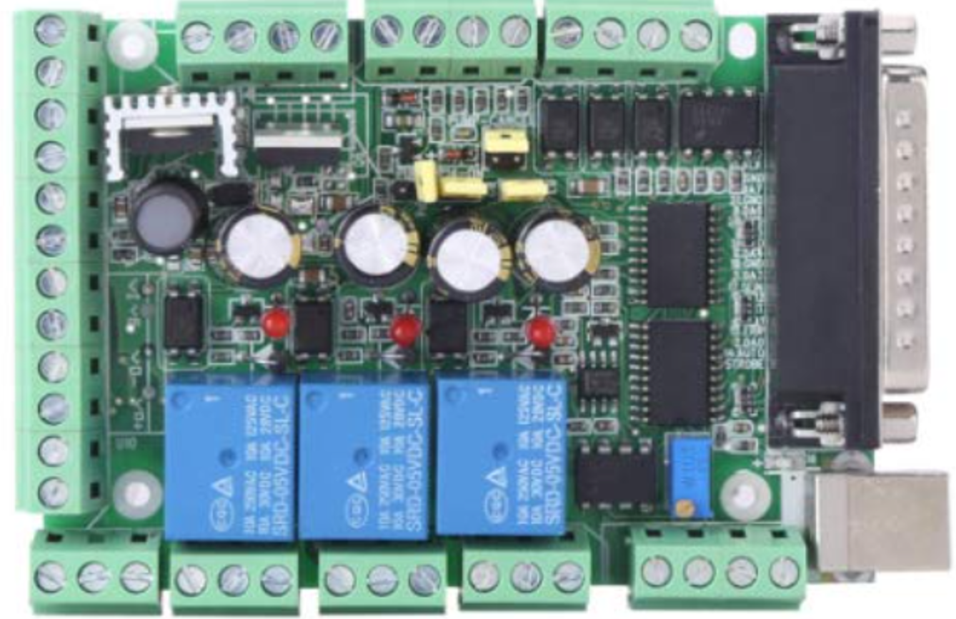
The Mach3 V2.1L breakout board is a versatile interface device designed to connect a computer to a CNC machine. This board facilitates the control of stepper motors and other CNC components through a parallel port or USB connection. It is widely used in DIY CNC projects, small-scale manufacturing, and educational purposes due to its ease of use and compatibility with the popular Mach3 CNC control software.
Explore Projects Built with mach3v2.1l break out board
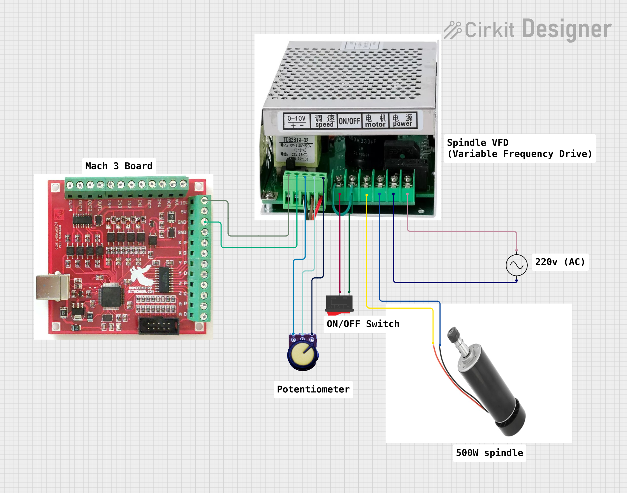

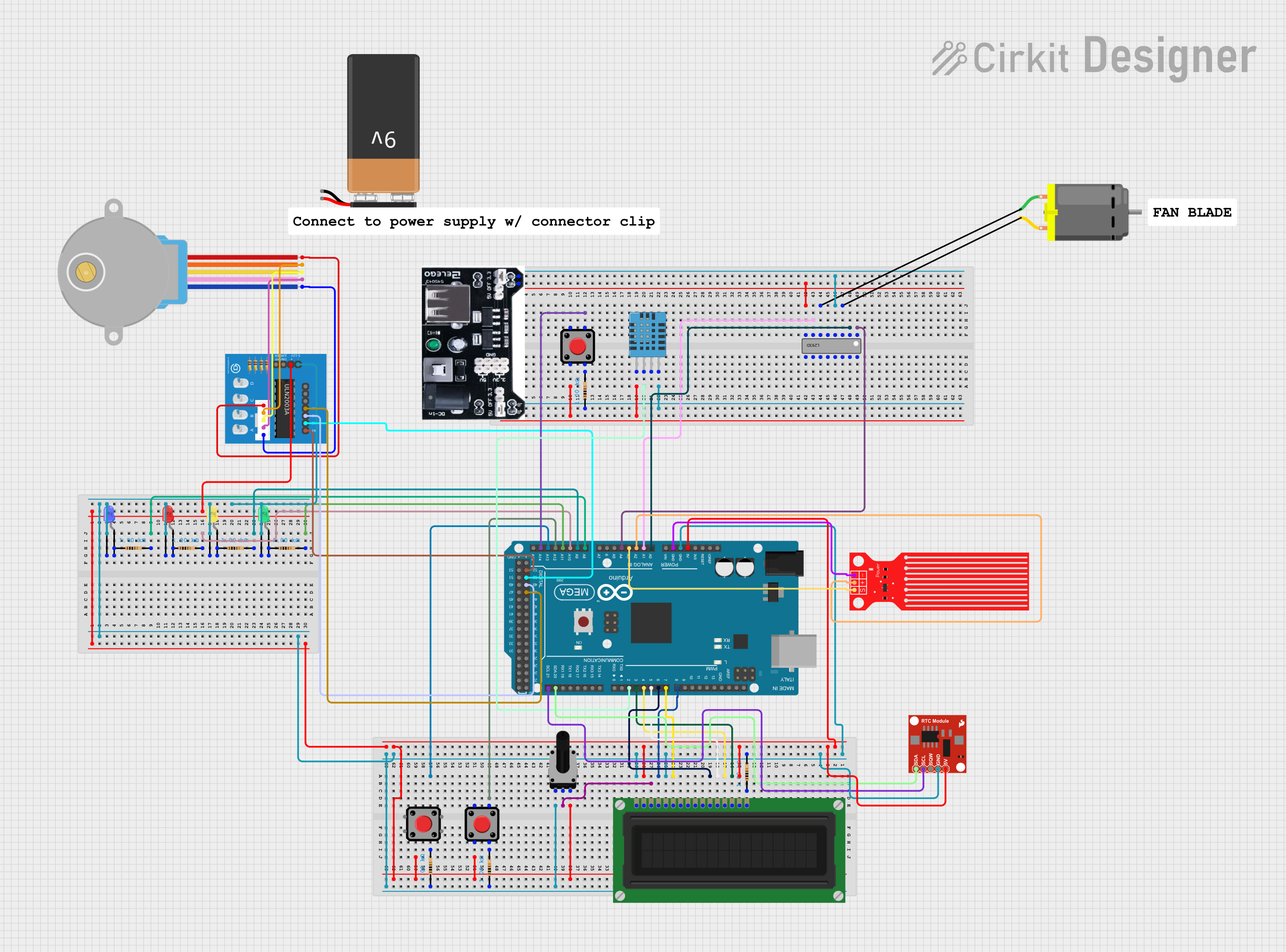
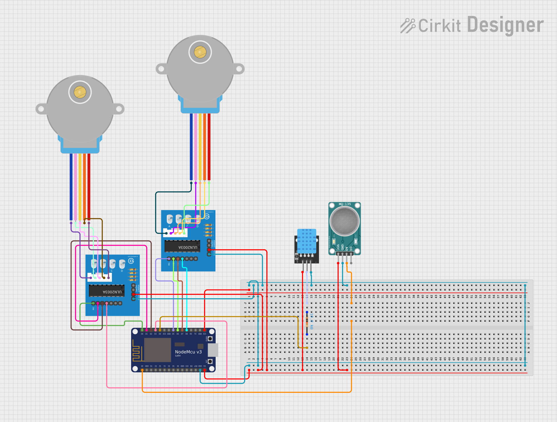
Explore Projects Built with mach3v2.1l break out board
Common Applications and Use Cases
- DIY CNC Machines: Ideal for hobbyists building their own CNC machines.
- Small-Scale Manufacturing: Used in small workshops for precise control of CNC machinery.
- Educational Projects: Employed in educational settings to teach CNC machine control and automation.
- Prototyping: Useful for rapid prototyping and testing of CNC systems.
Technical Specifications
Key Technical Details
| Specification | Value |
|---|---|
| Operating Voltage | 5V DC |
| Communication | Parallel Port / USB |
| Stepper Motor Control | Up to 4 axes |
| Input Pins | 5 (for limit switches, etc.) |
| Output Pins | 12 (for motor drivers, relays) |
| Dimensions | 90mm x 70mm x 20mm |
Pin Configuration and Descriptions
Parallel Port Pin Configuration
| Pin Number | Function | Description |
|---|---|---|
| 1 | X Step | Step signal for X-axis stepper motor |
| 2 | X Direction | Direction signal for X-axis stepper motor |
| 3 | Y Step | Step signal for Y-axis stepper motor |
| 4 | Y Direction | Direction signal for Y-axis stepper motor |
| 5 | Z Step | Step signal for Z-axis stepper motor |
| 6 | Z Direction | Direction signal for Z-axis stepper motor |
| 7 | A Step | Step signal for A-axis stepper motor |
| 8 | A Direction | Direction signal for A-axis stepper motor |
| 9 | Enable | Enable signal for all stepper motors |
| 10 | Limit Switch X | Input for X-axis limit switch |
| 11 | Limit Switch Y | Input for Y-axis limit switch |
| 12 | Limit Switch Z | Input for Z-axis limit switch |
| 13 | Emergency Stop | Input for emergency stop button |
| 14 | Spindle Control | Output for spindle motor control |
| 15 | Coolant Control | Output for coolant system control |
| 16 | Relay Control | Output for auxiliary relay control |
| 17 | Ground | Common ground |
| 18-25 | Ground | Common ground |
Usage Instructions
How to Use the Component in a Circuit
- Power Supply: Connect a 5V DC power supply to the breakout board.
- Stepper Motors: Connect the stepper motors to the corresponding step and direction pins.
- Limit Switches: Connect limit switches to the input pins for safety and precision.
- Emergency Stop: Connect an emergency stop button to the designated input pin.
- Spindle and Coolant Control: Connect the spindle motor and coolant system to the respective output pins.
- Communication: Connect the breakout board to the computer via the parallel port or USB.
Important Considerations and Best Practices
- Power Supply: Ensure a stable 5V DC power supply to avoid damage to the board.
- Wiring: Double-check all connections to prevent short circuits and incorrect wiring.
- Grounding: Properly ground the breakout board to avoid electrical noise and interference.
- Software Configuration: Configure the Mach3 software settings to match the pin configuration of the breakout board.
- Safety: Always use limit switches and an emergency stop button for safe operation.
Troubleshooting and FAQs
Common Issues Users Might Face
Stepper Motors Not Moving:
- Solution: Check the power supply and ensure all connections are secure. Verify the Mach3 software settings.
Limit Switches Not Responding:
- Solution: Ensure the limit switches are properly connected to the input pins. Check for any wiring issues.
Spindle Motor Not Controlling:
- Solution: Verify the spindle control output pin connection. Check the Mach3 software configuration.
Communication Issues:
- Solution: Ensure the parallel port or USB connection is secure. Update the drivers if necessary.
Solutions and Tips for Troubleshooting
- Check Connections: Regularly inspect all connections for loose wires or poor contacts.
- Update Software: Keep the Mach3 software and drivers up to date for optimal performance.
- Use Multimeter: Utilize a multimeter to check for continuity and proper voltage levels.
- Consult Forums: Engage with online CNC forums and communities for additional support and advice.
Example Code for Arduino UNO
If you are using the Mach3 V2.1L breakout board with an Arduino UNO for additional control, here is an example code snippet to control a stepper motor:
// Define pin connections
const int stepPin = 2; // Step signal pin
const int dirPin = 3;  // Direction signal pin

void setup() {
  // Set pin modes
  pinMode(stepPin, OUTPUT);
  pinMode(dirPin, OUTPUT);
}

void loop() {
  // Set direction
  digitalWrite(dirPin, HIGH); // Set direction to clockwise

  // Generate step signal
  for (int i = 0; i < 200; i++) { // 200 steps for one revolution
    digitalWrite(stepPin, HIGH);
    delayMicroseconds(1000); // Adjust delay for speed control
    digitalWrite(stepPin, LOW);
    delayMicroseconds(1000);
  }

  delay(1000); // Wait for a second

  // Change direction
  digitalWrite(dirPin, LOW); // Set direction to counterclockwise

  // Generate step signal
  for (int i = 0; i < 200; i++) {
    digitalWrite(stepPin, HIGH);
    delayMicroseconds(1000);
    digitalWrite(stepPin, LOW);
    delayMicroseconds(1000);
  }

  delay(1000); // Wait for a second
}
This code demonstrates how to control a stepper motor using the Mach3 V2.1L breakout board connected to an Arduino UNO. Adjust the pin connections and delay values as needed for your specific setup.
This documentation provides a comprehensive guide to the Mach3 V2.1L breakout board, covering its technical specifications, usage instructions, and troubleshooting tips. Whether you are a beginner or an experienced user, this guide will help you effectively utilize the breakout board in your CNC projects.