How to Use Multiplexer: Examples, Pinouts, and Specs
Introduction
The TCA9548A multiplexer, manufactured by hiBCTR, is an I2C-based device designed to select one of several input signals and forward the selected input to a single output line. This component is widely used in applications such as data routing, signal processing, and expanding the I2C bus to manage multiple devices with identical addresses. The TCA9548A is particularly useful in systems where multiple sensors or peripherals need to communicate over a shared I2C bus.
Explore Projects Built with Multiplexer


Explore Projects Built with Multiplexer
Common Applications:
- Expanding I2C bus capabilities
- Managing multiple devices with identical I2C addresses
- Signal routing in embedded systems
- Sensor arrays in robotics and IoT devices
Technical Specifications
Below are the key technical details of the TCA9548A multiplexer:
| Parameter | Value |
|---|---|
| Operating Voltage | 1.65V to 5.5V |
| I2C Address Range | 0x70 to 0x77 (configurable) |
| Maximum I2C Speed | 400 kHz (Fast Mode) |
| Channels | 8 (independent I2C buses) |
| Operating Temperature | -40°C to +85°C |
| Package Type | TSSOP-24 |
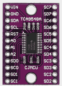
Pin Configuration and Descriptions
The TCA9548A comes in a 24-pin TSSOP package. Below is the pin configuration:
| Pin Number | Pin Name | Description |
|---|---|---|
| 1-8 | SD0-SD7 | I2C data lines for channels 0 to 7 |
| 9 | GND | Ground connection |
| 10 | VCC | Power supply input (1.65V to 5.5V) |
| 11 | SCL | I2C clock line (shared across all channels) |
| 12 | SDA | I2C data line (shared across all channels) |
| 13-15 | A0-A2 | Address selection pins (used to configure the I2C address of the multiplexer) |
| 16-23 | SC0-SC7 | I2C clock lines for channels 0 to 7 |
| 24 | RESET | Active-low reset pin |
Usage Instructions
How to Use the TCA9548A in a Circuit
- Power Supply: Connect the VCC pin to a power source within the range of 1.65V to 5.5V and the GND pin to ground.
- I2C Bus Connection: Connect the SDA and SCL pins to the I2C bus of your microcontroller or host device.
- Address Configuration: Use the A0, A1, and A2 pins to set the I2C address of the multiplexer. The address is determined by the binary state of these pins (e.g., 0x70 for all low, 0x77 for all high).
- Channel Selection: To communicate with a specific channel, send a command over the I2C bus to select the desired channel. Each channel corresponds to a bit in the control register.
- Peripheral Connection: Connect the I2C devices to the corresponding SDx and SCx pins of the selected channel.
Important Considerations and Best Practices
- Pull-Up Resistors: Ensure that appropriate pull-up resistors are used on the SDA and SCL lines of the I2C bus.
- Reset Pin: Use the RESET pin to reset the device if communication issues occur.
- Voltage Compatibility: Verify that the voltage levels of the connected devices are compatible with the TCA9548A.
- Channel Isolation: Only one channel can be active at a time. Ensure proper channel selection to avoid communication conflicts.
Example Code for Arduino UNO
Below is an example of how to use the TCA9548A with an Arduino UNO to communicate with a device on channel 0:
#include <Wire.h> // Include the Wire library for I2C communication

#define TCA9548A_ADDRESS 0x70 // Default I2C address of the TCA9548A

void selectChannel(uint8_t channel) {
  if (channel > 7) return; // Ensure the channel is within the valid range (0-7)
  Wire.beginTransmission(TCA9548A_ADDRESS);
  Wire.write(1 << channel); // Send the command to select the desired channel
  Wire.endTransmission();
}

void setup() {
  Wire.begin(); // Initialize the I2C bus
  Serial.begin(9600); // Initialize serial communication for debugging

  Serial.println("Selecting channel 0...");
  selectChannel(0); // Select channel 0
}

void loop() {
  // Add your code to communicate with the device on channel 0
  delay(1000); // Delay for demonstration purposes
}
Troubleshooting and FAQs
Common Issues and Solutions
Issue: The multiplexer does not respond to I2C commands.
- Solution: Verify the I2C address configuration (A0, A1, A2 pins). Ensure pull-up resistors are present on the SDA and SCL lines.
Issue: Communication with devices on specific channels fails.
- Solution: Check the wiring of the SDx and SCx pins for the affected channel. Ensure the connected devices are powered and functioning correctly.
Issue: Multiple channels appear active simultaneously.
- Solution: Ensure that only one channel is selected at a time by writing the appropriate value to the control register.
FAQs
Q: Can I use the TCA9548A with 3.3V and 5V devices simultaneously?
A: Yes, the TCA9548A supports level shifting, allowing it to interface with devices operating at different voltage levels.Q: How many TCA9548A devices can I use on the same I2C bus?
A: Up to 8 devices can be used by configuring unique I2C addresses using the A0, A1, and A2 pins.Q: What happens if no channel is selected?
A: If no channel is selected, the TCA9548A will not forward any I2C communication to the connected devices.
This concludes the documentation for the TCA9548A multiplexer. For further assistance, refer to the manufacturer's datasheet or contact technical support.