
How to Use XT30 Connector: Examples, Pinouts, and Specs
 Design with XT30 Connector in Cirkit Designer
Introduction
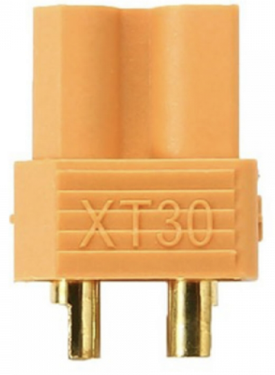
The XT30 Connector is a compact and lightweight electrical connector designed for high-current applications. It is widely used in remote-controlled (RC) vehicles, drones, and other battery-powered devices due to its ability to handle currents of up to 30A. The connector features a secure locking mechanism that ensures a reliable connection, even in environments subject to vibration or movement. Its small size and robust design make it an ideal choice for applications where space and weight are critical considerations.
Explore Projects Built with XT30 Connector
 Open Project in Cirkit Designer
 Open Project in Cirkit Designer
 Open Project in Cirkit Designer
 Open Project in Cirkit Designer
Explore Projects Built with XT30 Connector
Open Project in Cirkit DesignerOpen Project in Cirkit DesignerOpen Project in Cirkit DesignerOpen Project in Cirkit DesignerCommon Applications
- RC vehicles (cars, boats, planes)
- Drones and quadcopters
- Battery packs for portable devices
- Robotics and small-scale industrial equipment
- DIY electronics projects requiring high-current connections
Technical Specifications
The XT30 Connector is designed to provide a reliable and efficient connection for high-current circuits. Below are its key technical details:
Key Specifications
| Parameter | Value |
|---|---|
| Rated Current | Up to 30A |
| Voltage Rating | Up to 500V DC |
| Contact Resistance | ≤ 0.85 mΩ |
| Operating Temperature | -20°C to 120°C |
| Connector Material | Nylon (heat-resistant) |
| Contact Material | Gold-plated brass |
| Weight (per connector) | ~2.3g |
Pin Configuration and Descriptions
The XT30 Connector consists of two main pins: a positive (+) pin and a negative (-) pin. These pins are polarized to prevent incorrect connections.
| Pin Name | Description |
|---|---|
| Positive (+) | Connects to the positive terminal of the power source or load |
| Negative (-) | Connects to the negative terminal of the power source or load |
The connector is typically sold in pairs, with one male and one female connector. The male connector has exposed pins, while the female connector has recessed sockets for safety.
Usage Instructions
How to Use the XT30 Connector in a Circuit
Soldering the Wires:
- Strip the insulation from the wires you intend to connect to the XT30.
- Tin the exposed wire ends with solder to ensure a strong connection.
- Heat the solder cups on the XT30 connector and insert the tinned wire ends. Apply solder to secure the connection.
- Ensure the positive wire is connected to the positive pin and the negative wire to the negative pin.
Heat Shrink Tubing:
- Slide heat shrink tubing over the soldered connections to insulate and protect them.
- Use a heat gun to shrink the tubing securely around the connections.
Connecting the XT30:
- Align the male and female connectors, ensuring the polarity matches.
- Push the connectors together until the locking mechanism clicks into place.
Important Considerations
- Polarity: Always double-check the polarity before connecting the XT30 to avoid damaging your circuit or components.
- Wire Gauge: Use an appropriate wire gauge (e.g., 16-18 AWG) to handle the current without overheating.
- Soldering Temperature: Use a soldering iron with a temperature of 350-400°C for optimal results.
- Secure Mounting: If the XT30 is used in a high-vibration environment, consider securing it with zip ties or mounting brackets.
Example: Connecting an XT30 to an Arduino UNO
While the XT30 is not directly connected to an Arduino UNO, it can be used to supply power to the Arduino via a battery pack. Below is an example of how to use the XT30 in such a setup:
- Connect the XT30 to a battery pack.
- Use a voltage regulator (e.g., LM7805) to step down the battery voltage to 5V.
- Connect the output of the voltage regulator to the Arduino's 5V and GND pins.
// Example Arduino code to blink an LED when powered via an XT30-connected battery

void setup() {
  pinMode(13, OUTPUT); // Set pin 13 as an output for the LED
}

void loop() {
  digitalWrite(13, HIGH); // Turn the LED on
  delay(1000);            // Wait for 1 second
  digitalWrite(13, LOW);  // Turn the LED off
  delay(1000);            // Wait for 1 second
}
Troubleshooting and FAQs
Common Issues
Loose Connections:
- Problem: The XT30 connector feels loose or disconnects easily.
- Solution: Ensure the connectors are fully mated and the locking mechanism is engaged. Check for wear or damage to the connector.
Overheating:
- Problem: The connector becomes hot during use.
- Solution: Verify that the current does not exceed the 30A rating. Use appropriate wire gauge and ensure solder joints are secure.
Incorrect Polarity:
- Problem: The circuit does not work or components are damaged.
- Solution: Double-check the polarity of the connections before powering the circuit.
Soldering Issues:
- Problem: Wires detach from the connector or poor conductivity is observed.
- Solution: Ensure proper soldering technique and use high-quality solder. Avoid cold solder joints.
FAQs
Q: Can the XT30 handle more than 30A?
A: While the XT30 is rated for up to 30A, exceeding this limit may cause overheating or damage. For higher currents, consider using an XT60 or XT90 connector.
Q: Is the XT30 waterproof?
A: No, the XT30 is not inherently waterproof. If water resistance is required, use additional protective measures such as waterproof enclosures or sealants.
Q: Can I use the XT30 for AC applications?
A: The XT30 is primarily designed for DC applications. Using it for AC is not recommended due to potential safety and performance issues.
Q: How do I disconnect the XT30?
A: Firmly grip both connectors and pull them apart while avoiding excessive force. Do not pull on the wires to disconnect.
By following this documentation, you can effectively use the XT30 Connector in your projects and ensure reliable performance.