Cirkit Designer Logo
Cirkit Designer
Your all-in-one circuit design IDE
Home / 
Component Documentation

How to Use Piezo Sensor Module: Examples, Pinouts, and Specs

Image of Piezo Sensor Module
Cirkit Designer LogoDesign with Piezo Sensor Module in Cirkit Designer

Introduction

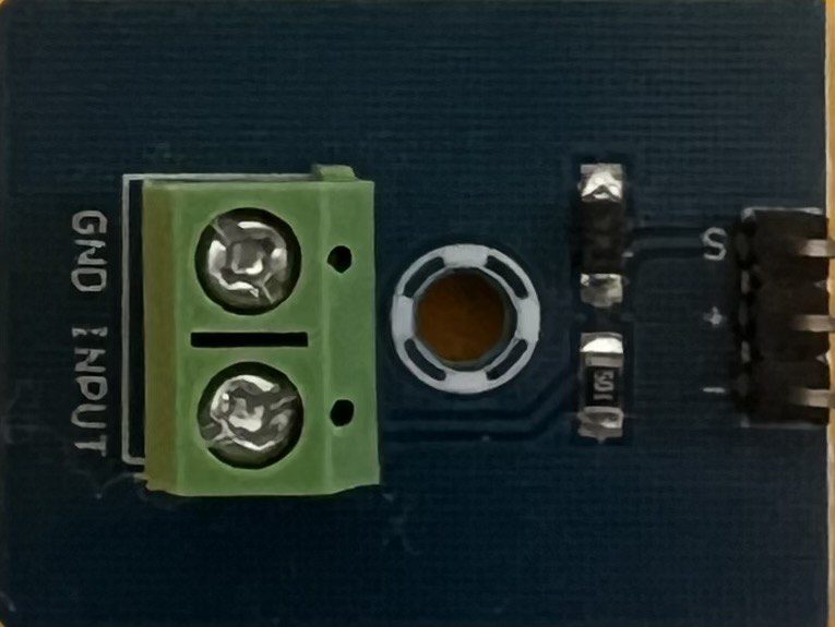
The Piezo Sensor Module is a device that converts mechanical stress, vibrations, or pressure into an electrical signal. It leverages the piezoelectric effect, where certain materials generate an electric charge in response to applied mechanical force. This module is widely used in applications requiring sound detection, vibration monitoring, or pressure sensing.

Explore Projects Built with Piezo Sensor Module

Use Cirkit Designer to design, explore, and prototype these projects online. Some projects support real-time simulation. Click "Open Project" to start designing instantly!
Battery-Powered Piezo Sensor Array with PowerBoost and Bridge Rectifier
Image of Copy of PIEZOELECTRIC : A project utilizing Piezo Sensor Module in a practical application
This circuit uses multiple piezo sensors connected to bridge rectifiers to convert AC signals from the sensors into DC. The rectified DC is then used to charge a 18650 Li-ion battery, which powers a PowerBoost 1000 Basic module to provide a stable 5V output.
Cirkit Designer LogoOpen Project in Cirkit Designer
Arduino Nano-Based Piezo Sensor Data Logger with SD Card Storage
Image of piezo tester: A project utilizing Piezo Sensor Module in a practical application
This circuit connects a piezo sensor to an Arduino Nano for the purpose of reading voltage signals generated by the sensor. The Arduino Nano is also interfaced with a Micro SD Card Module via SPI to log the sensor data. The code provided enables the Arduino to read the sensor's voltage at a rate of 10 times per second and store this data on the SD card.
Cirkit Designer LogoOpen Project in Cirkit Designer
Arduino Nano-Based Piezo Sensor Data Logger with SD Card Storage
Image of sd card test: A project utilizing Piezo Sensor Module in a practical application
This circuit features an Arduino Nano interfaced with a piezo sensor and a micro SD card module. The piezo sensor's output is connected to the Arduino's analog input A0 for voltage measurement, while the SD card module is connected via SPI to the digital pins D10 (CS), D11 (MOSI), D12 (MISO), and D13 (SCK) for data logging. The Arduino runs a sketch that reads the sensor data, converts it to voltage, and logs it to a text file on the SD card at one-second intervals.
Cirkit Designer LogoOpen Project in Cirkit Designer
Piezo Sensor Array with LED Indicator and Bridge Rectifier
Image of Project: A project utilizing Piezo Sensor Module in a practical application
This circuit consists of multiple piezo sensors connected in parallel to a bridge rectifier, which converts the AC signals from the sensors into DC. The rectified output is then filtered by an electrolytic capacitor and used to power a red LED, indicating the presence of vibrations or mechanical stress detected by the piezo sensors.
Cirkit Designer LogoOpen Project in Cirkit Designer

Explore Projects Built with Piezo Sensor Module

Use Cirkit Designer to design, explore, and prototype these projects online. Some projects support real-time simulation. Click "Open Project" to start designing instantly!
Image of Copy of PIEZOELECTRIC : A project utilizing Piezo Sensor Module in a practical application
Battery-Powered Piezo Sensor Array with PowerBoost and Bridge Rectifier
This circuit uses multiple piezo sensors connected to bridge rectifiers to convert AC signals from the sensors into DC. The rectified DC is then used to charge a 18650 Li-ion battery, which powers a PowerBoost 1000 Basic module to provide a stable 5V output.
Cirkit Designer LogoOpen Project in Cirkit Designer
Image of piezo tester: A project utilizing Piezo Sensor Module in a practical application
Arduino Nano-Based Piezo Sensor Data Logger with SD Card Storage
This circuit connects a piezo sensor to an Arduino Nano for the purpose of reading voltage signals generated by the sensor. The Arduino Nano is also interfaced with a Micro SD Card Module via SPI to log the sensor data. The code provided enables the Arduino to read the sensor's voltage at a rate of 10 times per second and store this data on the SD card.
Cirkit Designer LogoOpen Project in Cirkit Designer
Image of sd card test: A project utilizing Piezo Sensor Module in a practical application
Arduino Nano-Based Piezo Sensor Data Logger with SD Card Storage
This circuit features an Arduino Nano interfaced with a piezo sensor and a micro SD card module. The piezo sensor's output is connected to the Arduino's analog input A0 for voltage measurement, while the SD card module is connected via SPI to the digital pins D10 (CS), D11 (MOSI), D12 (MISO), and D13 (SCK) for data logging. The Arduino runs a sketch that reads the sensor data, converts it to voltage, and logs it to a text file on the SD card at one-second intervals.
Cirkit Designer LogoOpen Project in Cirkit Designer
Image of Project: A project utilizing Piezo Sensor Module in a practical application
Piezo Sensor Array with LED Indicator and Bridge Rectifier
This circuit consists of multiple piezo sensors connected in parallel to a bridge rectifier, which converts the AC signals from the sensors into DC. The rectified output is then filtered by an electrolytic capacitor and used to power a red LED, indicating the presence of vibrations or mechanical stress detected by the piezo sensors.
Cirkit Designer LogoOpen Project in Cirkit Designer

Common Applications and Use Cases

  • Sound detection (e.g., clapping or knocking)
  • Vibration monitoring in machinery
  • Pressure sensing in touch-sensitive devices
  • Impact detection in security systems
  • Musical instruments and audio pickups

Technical Specifications

Below are the key technical details and pin configuration for the Piezo Sensor Module:

Key Technical Details

Parameter Value
Operating Voltage 3.3V to 5V
Output Signal Type Analog or Digital (depending on module)
Sensitivity Range High sensitivity to vibrations
Output Voltage Range 0V to Vcc (depending on force applied)
Dimensions Varies by module (e.g., 28mm x 15mm)
Operating Temperature -20°C to 70°C

Pin Configuration

Pin Name Description
VCC Power supply pin (3.3V to 5V)
GND Ground pin
OUT Output pin (Analog or Digital signal)

Usage Instructions

How to Use the Piezo Sensor Module in a Circuit

  1. Connect the Module to Power:

    • Connect the VCC pin to a 3.3V or 5V power source.
    • Connect the GND pin to the ground of your circuit.
  2. Connect the Output Pin:

    • For analog output, connect the OUT pin to an analog input pin of your microcontroller.
    • For digital output (if the module has a comparator), connect the OUT pin to a digital input pin.
  3. Place the Sensor:

    • Mount the sensor in a location where it can detect vibrations, sound, or pressure effectively.
  4. Read the Signal:

    • For analog output, read the voltage signal using an ADC (Analog-to-Digital Converter) on your microcontroller.
    • For digital output, monitor the HIGH or LOW state of the OUT pin.

Important Considerations and Best Practices

  • Avoid Overloading: Do not apply excessive force to the piezo element, as it may damage the sensor.
  • Noise Filtering: Use capacitors or software filtering to reduce noise in the output signal.
  • Mounting: Ensure the sensor is securely mounted to avoid false readings due to unintended vibrations.
  • Voltage Compatibility: Verify that the module's operating voltage matches your microcontroller's input voltage.

Example: Connecting to an Arduino UNO

Below is an example of how to use the Piezo Sensor Module with an Arduino UNO to detect vibrations:

// Piezo Sensor Module Example with Arduino UNO
// This code reads the analog signal from the piezo sensor and prints it to the Serial Monitor.

const int piezoPin = A0; // Connect the OUT pin of the module to Arduino pin A0

void setup() {
  Serial.begin(9600); // Initialize serial communication at 9600 baud
  pinMode(piezoPin, INPUT); // Set the piezo pin as an input
}

void loop() {
  int sensorValue = analogRead(piezoPin); // Read the analog value from the sensor
  Serial.print("Piezo Sensor Value: ");
  Serial.println(sensorValue); // Print the sensor value to the Serial Monitor
  delay(100); // Delay for 100ms to avoid flooding the Serial Monitor
}

Troubleshooting and FAQs

Common Issues and Solutions

  1. No Output Signal:

    • Cause: Loose connections or insufficient power supply.
    • Solution: Check all connections and ensure the module is powered with the correct voltage.
  2. Inconsistent Readings:

    • Cause: Electrical noise or unstable mounting.
    • Solution: Add a capacitor (e.g., 0.1µF) across the OUT pin and ground to filter noise. Securely mount the sensor to reduce false readings.
  3. Output Always HIGH or LOW:

    • Cause: Faulty module or incorrect wiring.
    • Solution: Verify the wiring and test the module with a multimeter or another microcontroller.

FAQs

Q: Can the Piezo Sensor Module detect sound?
A: Yes, it can detect sound vibrations, such as clapping or knocking, but it is not as sensitive as a dedicated microphone.

Q: How do I increase the sensitivity of the sensor?
A: You can amplify the output signal using an operational amplifier or adjust the placement of the sensor for better detection.

Q: Can I use the Piezo Sensor Module with a 3.3V microcontroller?
A: Yes, the module typically works with both 3.3V and 5V systems. Check the specific module's datasheet to confirm compatibility.

Q: Is the Piezo Sensor Module waterproof?
A: Most modules are not waterproof. If you need to use it in a wet environment, consider waterproofing the sensor or using a sealed module.