How to Use Signal-Relais, 5 V DC, 3 A, 2 CO: Examples, Pinouts, and Specs
Introduction
The Signal-Relais AZ832-2C-5DE by Zettler is a compact, high-performance electromechanical relay designed for low-power signal switching applications. It operates on a 5 V DC control signal and can handle currents of up to 3 A. This relay features 2 changeover (CO) contacts, making it suitable for versatile switching configurations. Its small size and reliable performance make it ideal for applications in telecommunications, industrial control systems, home automation, and more.
Explore Projects Built with Signal-Relais, 5 V DC, 3 A, 2 CO


Explore Projects Built with Signal-Relais, 5 V DC, 3 A, 2 CO
Common Applications
- Signal switching in telecommunications equipment
- Industrial automation and control systems
- Home automation circuits
- Low-power motor control
- Audio and video equipment switching
Technical Specifications
Key Specifications
| Parameter | Value |
|---|---|
| Manufacturer | Zettler |
| Part Number | AZ832-2C-5DE |
| Coil Voltage | 5 V DC |
| Contact Configuration | 2 Changeover (2 CO) |
| Maximum Switching Current | 3 A |
| Maximum Switching Voltage | 250 V AC / 30 V DC |
| Coil Resistance | 178 Ω ±10% |
| Power Consumption | Approximately 140 mW |
| Dielectric Strength | 1000 V AC (coil to contacts) |
| Operating Temperature | -40°C to +85°C |
| Dimensions | 20.2 mm x 10.2 mm x 10.6 mm |
Pin Configuration and Descriptions
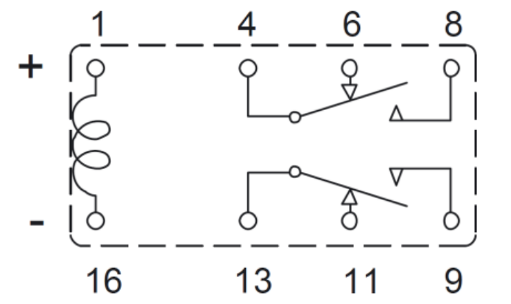
The AZ832-2C-5DE relay has a total of 8 pins. The pinout is as follows:
| Pin Number | Description |
|---|---|
| 1 | Coil Terminal 1 (Positive) |
| 2 | Coil Terminal 2 (Negative) |
| 3 | Common Contact 1 (COM1) |
| 4 | Normally Closed Contact 1 (NC1) |
| 5 | Normally Open Contact 1 (NO1) |
| 6 | Common Contact 2 (COM2) |
| 7 | Normally Closed Contact 2 (NC2) |
| 8 | Normally Open Contact 2 (NO2) |
Usage Instructions
How to Use the Component in a Circuit
- Power the Coil: Connect the relay's coil terminals (pins 1 and 2) to a 5 V DC power source. Ensure the polarity is correct: pin 1 is positive, and pin 2 is negative.
- Control the Circuit: Use the relay's contacts (pins 3–8) to control the desired circuit. The relay provides two independent changeover (CO) contacts:
- When the coil is not energized, the common (COM) pins are connected to the normally closed (NC) pins.
- When the coil is energized, the common (COM) pins are connected to the normally open (NO) pins.
- Load Connection: Connect the load to the appropriate contact pins (NO or NC) based on your application requirements.
Important Considerations and Best Practices
- Diode Protection: Always connect a flyback diode across the coil terminals to protect the driving circuit from voltage spikes when the relay is de-energized.
- Current Ratings: Ensure the load current does not exceed the relay's maximum switching current of 3 A.
- Isolation: Maintain proper isolation between the coil and contact circuits to prevent interference or damage.
- Mounting: Secure the relay on a PCB or socket to ensure stable operation and avoid mechanical stress.
Example: Connecting to an Arduino UNO
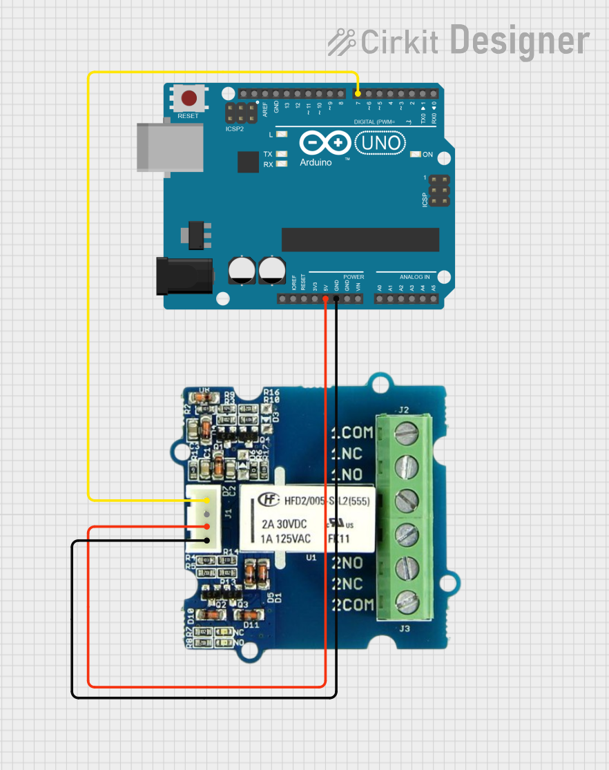
The AZ832-2C-5DE relay can be controlled using an Arduino UNO. Below is an example circuit and code to toggle the relay:
Circuit Diagram
- Connect pin 1 of the relay to a digital output pin on the Arduino (e.g., pin 7) through a transistor and a 1 kΩ base resistor.
- Connect pin 2 of the relay to the Arduino's GND.
- Add a flyback diode (e.g., 1N4007) across the relay coil terminals (pin 1 and pin 2) with the cathode connected to pin 1.
Arduino Code
// Define the relay control pin
const int relayPin = 7;

void setup() {
  // Set the relay pin as an output
  pinMode(relayPin, OUTPUT);
}

void loop() {
  // Turn the relay ON
  digitalWrite(relayPin, HIGH);
  delay(1000); // Keep the relay ON for 1 second

  // Turn the relay OFF
  digitalWrite(relayPin, LOW);
  delay(1000); // Keep the relay OFF for 1 second
}
Troubleshooting and FAQs
Common Issues and Solutions
Relay Not Switching
- Cause: Insufficient voltage or current to the coil.
- Solution: Verify that the coil is receiving 5 V DC and sufficient current. Check the power supply and connections.
Contacts Not Conducting
- Cause: Incorrect wiring or damaged contacts.
- Solution: Double-check the wiring and ensure the load is connected to the correct pins (NO or NC). Inspect the relay for physical damage.
Voltage Spikes Damaging the Circuit
- Cause: Lack of a flyback diode across the coil.
- Solution: Install a flyback diode (e.g., 1N4007) across the coil terminals to suppress voltage spikes.
Relay Heating Up
- Cause: Exceeding the maximum current rating.
- Solution: Ensure the load current does not exceed 3 A. Use a heat sink or cooling mechanism if necessary.
FAQs
Q1: Can this relay switch AC loads?
A1: Yes, the relay can switch AC loads up to 250 V, provided the current does not exceed 3 A.
Q2: Can I use this relay with a 3.3 V microcontroller?
A2: Yes, but you will need a transistor or relay driver circuit to step up the control voltage to 5 V.
Q3: What is the lifespan of this relay?
A3: The relay has a mechanical lifespan of approximately 10 million operations and an electrical lifespan of around 100,000 operations under rated load conditions.
Q4: Is the relay polarity-sensitive?
A4: The coil terminals (pins 1 and 2) are polarity-sensitive. Ensure correct polarity when connecting the power supply.