
How to Use AD8397: Examples, Pinouts, and Specs
 Design with AD8397 in Cirkit Designer
Introduction
The AD8397 is a high-speed, high-performance operational amplifier manufactured by Analog Devices. It is specifically designed to drive capacitive loads and deliver high output current, making it ideal for demanding applications. With its wide bandwidth, low distortion, and robust design, the AD8397 is well-suited for use in audio, video, and data communication systems.
Explore Projects Built with AD8397
 Open Project in Cirkit Designer
 Open Project in Cirkit Designer
 Open Project in Cirkit Designer
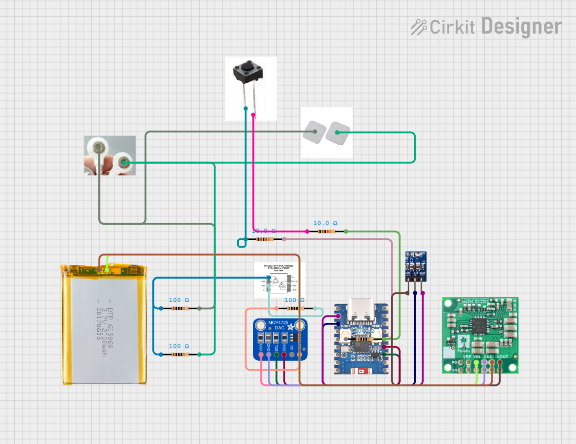 Open Project in Cirkit Designer
Explore Projects Built with AD8397
Open Project in Cirkit DesignerOpen Project in Cirkit DesignerOpen Project in Cirkit DesignerOpen Project in Cirkit DesignerCommon Applications
- Audio amplification systems
- Video signal processing
- Data communication equipment
- High-current buffer circuits
- Active filters and signal conditioning
Technical Specifications
The AD8397 offers exceptional performance characteristics, making it a versatile choice for a wide range of applications. Below are the key technical specifications:
| Parameter | Value |
|---|---|
| Supply Voltage Range | ±5 V to ±12 V or 10 V to 24 V |
| Output Current | Up to 310 mA |
| Bandwidth (−3 dB) | 69 MHz |
| Slew Rate | 53 V/µs |
| Total Harmonic Distortion | 0.0003% (at 1 kHz, 2 V p-p) |
| Input Offset Voltage | 1 mV (typical) |
| Input Bias Current | 1 µA (typical) |
| Operating Temperature Range | −40°C to +85°C |
| Package Options | 8-lead SOIC, 8-lead MSOP |
Pin Configuration and Descriptions
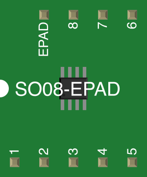
The AD8397 is available in an 8-lead SOIC or MSOP package. Below is the pinout and description:
| Pin Number | Pin Name | Description |
|---|---|---|
| 1 | OUTA | Output of Amplifier A |
| 2 | −INA | Inverting Input of Amplifier A |
| 3 | +INA | Non-Inverting Input of Amplifier A |
| 4 | V− | Negative Power Supply |
| 5 | +INB | Non-Inverting Input of Amplifier B |
| 6 | −INB | Inverting Input of Amplifier B |
| 7 | OUTB | Output of Amplifier B |
| 8 | V+ | Positive Power Supply |
Usage Instructions
The AD8397 is a dual operational amplifier that can be used in a variety of circuit configurations. Below are guidelines for using the component effectively:
Basic Circuit Configuration
To use the AD8397 in a typical amplifier circuit:
- Connect the V+ and V− pins to the appropriate power supply (e.g., ±12 V for dual supply or 24 V for single supply).
- Use decoupling capacitors (e.g., 0.1 µF ceramic and 10 µF electrolytic) close to the power supply pins to ensure stable operation.
- Connect the input signal to the +IN or −IN pins, depending on the desired configuration (non-inverting or inverting).
- Connect the output load to the OUT pin. Ensure the load impedance is within the amplifier's drive capability.
Important Considerations
- Thermal Management: The AD8397 can deliver high output current, which may cause heating. Ensure proper heat dissipation by using a PCB with adequate thermal management.
- Capacitive Loads: The AD8397 is designed to drive capacitive loads, but excessive capacitance may cause instability. Use a series resistor (e.g., 10 Ω) to improve stability if needed.
- Power Supply Decoupling: Always use decoupling capacitors to minimize noise and ensure stable operation.
Example: Using AD8397 with Arduino UNO
The AD8397 can be used to amplify signals for an Arduino-based project. Below is an example of interfacing the AD8397 with an Arduino UNO to amplify an analog signal:
Circuit Setup
- Connect the AD8397's V+ to +12 V and V− to −12 V.
- Connect the Arduino's analog output (e.g., pin A0) to the +INA pin of the AD8397.
- Connect the OUTA pin of the AD8397 to the input of an external device or measurement system.
- Use a resistor and capacitor network to set the gain and bandwidth as needed.
Arduino Code Example
// Example code to generate an analog signal for the AD8397 amplifier
// This code outputs a sine wave using PWM and a low-pass filter

const int pwmPin = 9; // PWM output pin
const int frequency = 1000; // Frequency of the sine wave in Hz
const int amplitude = 127; // Amplitude of the sine wave (0-255)
const int offset = 128; // DC offset for the sine wave (0-255)

void setup() {
  pinMode(pwmPin, OUTPUT); // Set the PWM pin as output
}

void loop() {
  for (int i = 0; i < 360; i++) {
    // Generate a sine wave using the sine function
    int value = offset + amplitude * sin(i * PI / 180);
    analogWrite(pwmPin, value); // Output the sine wave via PWM
    delayMicroseconds(1000000 / (frequency * 360)); // Control the frequency
  }
}
Note: Use a low-pass filter (e.g., RC filter) at the PWM output to smooth the signal before feeding it to the AD8397.
Troubleshooting and FAQs
Common Issues
Amplifier Instability:
- Cause: Excessive capacitive load or insufficient power supply decoupling.
- Solution: Add a series resistor (e.g., 10 Ω) to the output or improve decoupling with capacitors.
Overheating:
- Cause: High output current or inadequate thermal management.
- Solution: Use a heatsink or ensure proper PCB thermal design.
Distorted Output Signal:
- Cause: Input signal exceeds the amplifier's input range or insufficient power supply voltage.
- Solution: Verify input signal levels and ensure the power supply meets the required specifications.
FAQs
Q: Can the AD8397 operate with a single power supply?
A: Yes, the AD8397 can operate with a single supply voltage (e.g., 10 V to 24 V). Ensure the input signal is biased appropriately within the amplifier's input range.
Q: What is the maximum capacitive load the AD8397 can drive?
A: The AD8397 is designed to drive capacitive loads, but for optimal performance, it is recommended to use a series resistor to stabilize the output when driving large capacitances.
Q: Is the AD8397 suitable for audio applications?
A: Yes, the AD8397's low distortion and high output current make it an excellent choice for audio amplification systems.