Cirkit Designer
Your all-in-one circuit design IDE
Home /
Component Documentation
How to Use VC-02 Module: Examples, Pinouts, and Specs
Introduction
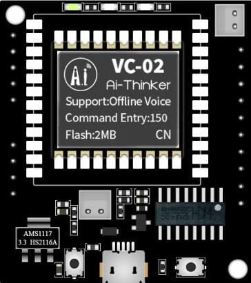
The VC-02 Module, manufactured by Ai-Thinker Technology Co., Ltd., is a Voltage Controlled Oscillator (VCO) designed for use in electronic circuits where frequency modulation is required. It is an essential component in synthesizers, audio equipment, and signal processing devices, allowing for the generation of waveforms whose frequency can be precisely controlled by varying the input voltage.
Explore Projects Built with VC-02 Module
Voice-Controlled Buzzer System with VC-02 Module

This circuit features a VC-02 voice recognition module connected to a buzzer and powered by a 5V battery. The VC-02 module is programmed to listen for specific voice commands and, upon recognizing the command 'can you make a sound', it activates the buzzer for one second. The circuit is designed for voice-activated sound generation, with the VC-02 module handling voice recognition and serial communication, and the buzzer providing audible feedback.
Arduino UNO and VC-02 Module Serial Communication Interface

This circuit connects an Arduino UNO with a VC-02 Module. The Arduino provides power to the VC-02 Module and establishes a serial communication interface, with the Arduino's D3 pin connected to the VC-02's RX pin and D2 to the VC-02's TX pin. The provided code suggests that the Arduino is configured to communicate with the VC-02 Module, but the specific functionality is not implemented in the given code skeleton.
Cellular-Enabled IoT Device with Real-Time Clock and Power Management

This circuit features a LilyGo-SIM7000G module for cellular communication and GPS functionality, interfaced with an RTC DS3231 for real-time clock capabilities. It includes voltage sensing through two voltage sensor modules, and uses an 8-channel opto-coupler for isolating different parts of the circuit. Power management is handled by a buck converter connected to a DC power source and batteries, with a fuse for protection and a rocker switch for on/off control. Additionally, there's an LED for indication purposes.
Arduino UNO and VC-02 Module-Based Voice-Controlled Stepper Motor System
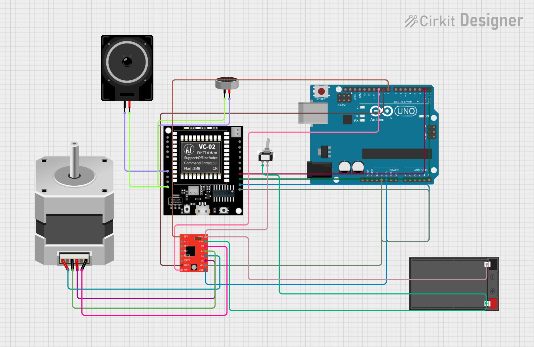
This circuit integrates an Arduino UNO to control a stepper motor via an A4988 driver and interfaces with a VC-02 module for audio processing. The condenser microphone captures audio signals, which are processed by the VC-02 module and output through a loudspeaker, while the Arduino also communicates with the VC-02 module and controls the stepper motor's movements.
Explore Projects Built with VC-02 Module
Voice-Controlled Buzzer System with VC-02 Module
This circuit features a VC-02 voice recognition module connected to a buzzer and powered by a 5V battery. The VC-02 module is programmed to listen for specific voice commands and, upon recognizing the command 'can you make a sound', it activates the buzzer for one second. The circuit is designed for voice-activated sound generation, with the VC-02 module handling voice recognition and serial communication, and the buzzer providing audible feedback.
Arduino UNO and VC-02 Module Serial Communication Interface
This circuit connects an Arduino UNO with a VC-02 Module. The Arduino provides power to the VC-02 Module and establishes a serial communication interface, with the Arduino's D3 pin connected to the VC-02's RX pin and D2 to the VC-02's TX pin. The provided code suggests that the Arduino is configured to communicate with the VC-02 Module, but the specific functionality is not implemented in the given code skeleton.
Cellular-Enabled IoT Device with Real-Time Clock and Power Management
This circuit features a LilyGo-SIM7000G module for cellular communication and GPS functionality, interfaced with an RTC DS3231 for real-time clock capabilities. It includes voltage sensing through two voltage sensor modules, and uses an 8-channel opto-coupler for isolating different parts of the circuit. Power management is handled by a buck converter connected to a DC power source and batteries, with a fuse for protection and a rocker switch for on/off control. Additionally, there's an LED for indication purposes.
Arduino UNO and VC-02 Module-Based Voice-Controlled Stepper Motor System
This circuit integrates an Arduino UNO to control a stepper motor via an A4988 driver and interfaces with a VC-02 module for audio processing. The condenser microphone captures audio signals, which are processed by the VC-02 module and output through a loudspeaker, while the Arduino also communicates with the VC-02 module and controls the stepper motor's movements.
Common Applications and Use Cases
- Audio synthesizers
- Frequency modulation (FM) synthesis
- Signal generators
- Electronic music production
- Test and measurement equipment
Technical Specifications
Key Technical Details
- Operating Voltage Range: 5V to 12V DC
- Frequency Range: 100 Hz to 20 kHz (typical)
- Output Waveforms: Sine, Square, Triangle
- Temperature Stability: ±0.5% (0°C to 70°C)
- Linearity: 0.1% (max deviation from linear frequency control)
Pin Configuration and Descriptions
| Pin Number | Name | Description |
|---|---|---|
| 1 | Vcc | Power supply input (5V to 12V DC) |
| 2 | GND | Ground connection |
| 3 | Vin | Voltage input for frequency control |
| 4 | OUT | Output signal |
| 5 | NC | No connection (reserved for future use) |
Usage Instructions
How to Use the VC-02 Module in a Circuit
- Power Supply: Connect the Vcc pin to a DC power supply within the specified operating voltage range. Ensure the GND pin is connected to the common ground of your circuit.
- Frequency Control Voltage: Apply a control voltage to the Vin pin to set the desired frequency of the output signal. The frequency is directly proportional to the input voltage.
- Output Signal: Connect the OUT pin to the next stage of your circuit (e.g., amplifier, mixer, or ADC) to utilize the generated waveform.
Important Considerations and Best Practices
- Avoid exceeding the maximum rated voltage to prevent damage to the module.
- Use a smooth and stable voltage source for Vin to maintain a stable frequency output.
- Shield the module from electromagnetic interference to prevent signal distortion.
- Ensure proper heat dissipation if operating near the upper limit of the voltage range.
Troubleshooting and FAQs
Common Issues and Solutions
- No Output Signal: Check power supply connections and ensure the input voltage is within the specified range. Verify that the control voltage is applied to the Vin pin.
- Unstable Frequency: Ensure that the control voltage source is stable. Use decoupling capacitors near the power supply pins if necessary.
- Distorted Output Waveform: Check for electromagnetic interference or improper grounding. Use shielded cables for connections, especially for the output signal.
FAQs
- Q: Can the VC-02 Module generate different waveforms?
- A: Yes, the VC-02 can generate sine, square, and triangle waveforms.
- Q: What is the maximum frequency the VC-02 can produce?
- A: The typical frequency range is from 100 Hz to 20 kHz, but it may vary slightly depending on the specific module and conditions.
- Q: Is the VC-02 compatible with Arduino UNO?
- A: Yes, it can be used with an Arduino UNO by connecting the Vcc to 5V, GND to ground, and controlling the Vin pin using a PWM output from the Arduino.
Example Arduino Code
// Example code to control VC-02 Module with Arduino UNO
int controlPin = 3; // PWM output connected to Vin of VC-02

void setup() {
  pinMode(controlPin, OUTPUT);
}

void loop() {
  // Generate a control voltage via PWM to set the frequency of VC-02
  analogWrite(controlPin, 128); // Set to 50% duty cycle for demonstration
  delay(1000); // Wait for 1 second

  // Change the frequency by adjusting the PWM signal
  analogWrite(controlPin, 64); // Set to 25% duty cycle
  delay(1000); // Wait for 1 second
}
Note: The above code is a simple demonstration. The actual frequency control will depend on the specific characteristics of the VC-02 Module and the input voltage applied to the Vin pin. Use a low-pass filter to convert the PWM signal to a DC voltage for finer control over the frequency.