How to Use off delay module: Examples, Pinouts, and Specs
Introduction
The Off Delay Module is an electronic device designed to delay the turn-off of a circuit after the trigger signal is removed. This functionality is essential in automation and control systems where controlled timing is required. By maintaining the circuit's operation for a specified duration after the trigger is deactivated, the module ensures smooth transitions and prevents abrupt interruptions.
Explore Projects Built with off delay module
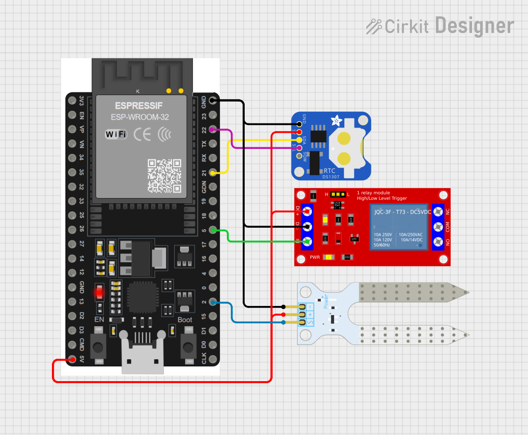

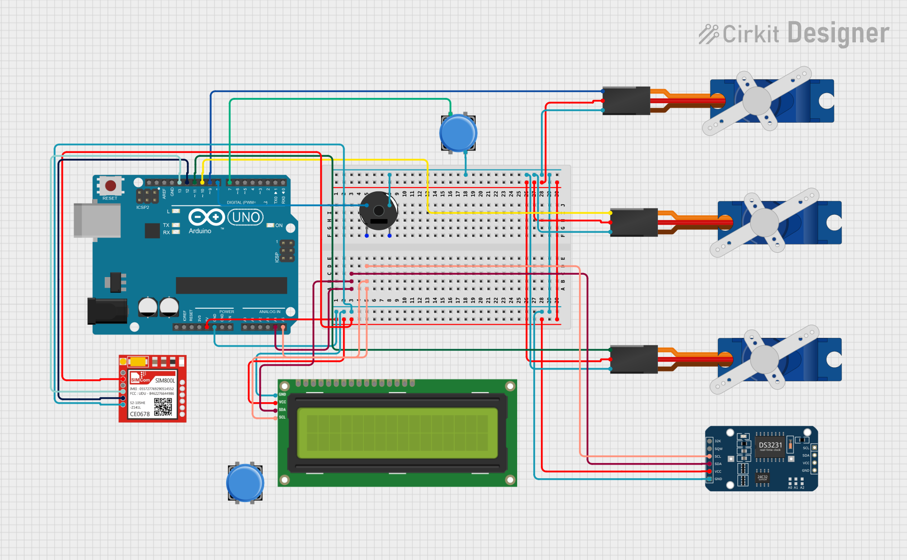

Explore Projects Built with off delay module
Common Applications and Use Cases
- Industrial automation systems for controlled shutdowns
- Lighting systems to provide delayed turn-off
- Motor control circuits to prevent sudden stops
- HVAC systems for post-operation cooling
- Security systems for timed alarms or notifications
Technical Specifications
The Off Delay Module is available in various configurations, but the following are typical specifications:
| Parameter | Value |
|---|---|
| Operating Voltage | 12V DC or 24V DC (model-dependent) |
| Current Rating | 10A (max load) |
| Delay Time Range | 0.1 seconds to 10 minutes |
| Trigger Signal Voltage | 3V to 24V DC |
| Power Consumption | < 1W |
| Operating Temperature | -20°C to 60°C |
| Dimensions | 50mm x 30mm x 20mm |
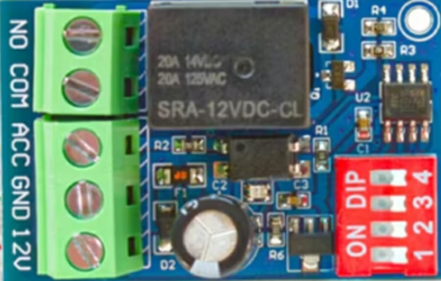
Pin Configuration and Descriptions
The Off Delay Module typically has the following pin configuration:
| Pin Name | Description |
|---|---|
| VCC | Positive power supply input (e.g., 12V or 24V DC) |
| GND | Ground connection for the power supply |
| TRIG | Trigger input pin; accepts a signal to activate the delay timer |
| OUT | Output pin; connected to the load that will remain active during the delay time |
Usage Instructions
How to Use the Off Delay Module in a Circuit
- Power the Module: Connect the VCC pin to a 12V or 24V DC power source (depending on the module's rating) and the GND pin to the ground.
- Connect the Trigger Signal: Attach the TRIG pin to the control signal source (e.g., a microcontroller, switch, or sensor). Ensure the signal voltage is within the specified range (3V to 24V DC).
- Connect the Load: Attach the load (e.g., a motor, light, or relay) to the OUT pin. Ensure the load does not exceed the module's current rating (10A).
- Set the Delay Time: Adjust the delay time using the onboard potentiometer or DIP switches (if available). Refer to the module's datasheet for specific adjustment instructions.
- Test the Circuit: Activate the trigger signal to start the delay timer. Once the trigger is removed, the load will remain active for the set delay time before turning off.
Important Considerations and Best Practices
- Power Supply: Ensure the power supply voltage matches the module's operating voltage.
- Load Compatibility: Verify that the load's current and voltage ratings are within the module's specifications.
- Signal Stability: Use a stable and noise-free trigger signal to avoid false triggering.
- Heat Dissipation: If operating at high currents, ensure proper ventilation or heat dissipation to prevent overheating.
- Polarity: Double-check the polarity of the power supply and connections to avoid damage to the module.
Example: Using the Off Delay Module with an Arduino UNO
The Off Delay Module can be triggered by an Arduino UNO. Below is an example code snippet:
// Example: Triggering an Off Delay Module with Arduino UNO
// This code sends a HIGH signal to the TRIG pin for 5 seconds, then removes it.
// The Off Delay Module will keep the load active for the set delay time.

const int trigPin = 7; // Arduino pin connected to the TRIG pin of the module

void setup() {
  pinMode(trigPin, OUTPUT); // Set the TRIG pin as an output
  digitalWrite(trigPin, LOW); // Ensure the TRIG pin starts LOW
}

void loop() {
  digitalWrite(trigPin, HIGH); // Send a HIGH signal to trigger the module
  delay(5000); // Keep the signal HIGH for 5 seconds
  digitalWrite(trigPin, LOW); // Remove the trigger signal
  delay(10000); // Wait for 10 seconds before repeating
}
Troubleshooting and FAQs
Common Issues and Solutions
| Issue | Possible Cause | Solution |
|---|---|---|
| Module does not activate the load | Incorrect power supply voltage | Verify the power supply voltage matches the module's specifications. |
| Load turns off immediately after trigger | Delay time not set correctly | Adjust the delay time using the potentiometer or DIP switches. |
| False triggering of the module | Noise or unstable trigger signal | Use a debounce circuit or filter to stabilize the trigger signal. |
| Module overheats during operation | Load exceeds the current rating | Ensure the load's current is within the module's maximum rating (10A). |
FAQs
Can the delay time be adjusted dynamically?
- Most modules allow manual adjustment via a potentiometer or DIP switches. For dynamic control, consider using a programmable timer circuit.
What happens if the trigger signal is reactivated during the delay period?
- The behavior depends on the module design. Some modules reset the delay timer, while others ignore the new trigger until the current delay period ends.
Can the module handle AC loads?
- The module is designed for DC loads. For AC loads, use a relay or solid-state relay compatible with the module's output.
Is the module compatible with 5V logic signals?
- Yes, the TRIG pin typically accepts signals as low as 3V, making it compatible with 5V logic systems like Arduino.
By following this documentation, users can effectively integrate the Off Delay Module into their projects for reliable and controlled timing operations.