How to Use Piezo Vibration Sensor: Examples, Pinouts, and Specs
Introduction
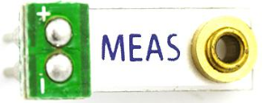
The Piezo Vibration Sensor is a device that detects vibrations and converts them into an electrical signal using the piezoelectric effect. This sensor is highly sensitive to mechanical vibrations and is commonly used in applications such as motion detection, impact monitoring, and vibration analysis. Its compact size and simplicity make it a versatile component for various projects, including security systems, industrial monitoring, and DIY electronics.
Explore Projects Built with Piezo Vibration Sensor
Explore Projects Built with Piezo Vibration Sensor
Technical Specifications
- Operating Voltage: 3.3V to 5V
- Output Signal: Analog voltage
- Sensitivity: High sensitivity to mechanical vibrations
- Operating Temperature: -20°C to 70°C
- Dimensions: Typically small and lightweight (varies by model)
- Material: Piezoelectric ceramic element
Pin Configuration and Descriptions
| Pin Name | Description |
|---|---|
| Signal | Outputs an analog voltage proportional to the detected vibration intensity. |
| VCC | Power supply pin (3.3V to 5V). |
| GND | Ground connection. |
Usage Instructions
How to Use the Piezo Vibration Sensor in a Circuit
Connect the Sensor:
- Connect the
VCCpin to a 3.3V or 5V power supply. - Connect the
GNDpin to the ground of your circuit. - Connect the
Signalpin to an analog input pin of your microcontroller or to an oscilloscope for signal monitoring.
- Connect the
Read the Output:
- The sensor outputs an analog voltage that corresponds to the intensity of the detected vibration. This signal can be read using an analog-to-digital converter (ADC) on a microcontroller.
Add a Resistor:
- For better signal stability, connect a pull-down resistor (e.g., 1MΩ) between the
Signalpin andGND.
- For better signal stability, connect a pull-down resistor (e.g., 1MΩ) between the
Optional Filtering:
- To reduce noise, you can add a capacitor (e.g., 0.1µF) between the
Signalpin andGND.
- To reduce noise, you can add a capacitor (e.g., 0.1µF) between the
Important Considerations and Best Practices
- Avoid exposing the sensor to extreme temperatures or excessive mechanical stress, as this may damage the piezoelectric element.
- Use proper shielding or filtering to minimize noise in the output signal.
- Mount the sensor securely to ensure accurate vibration detection.
- If using with a microcontroller, ensure the ADC resolution is sufficient to capture the signal variations.
Example: Connecting to an Arduino UNO
Below is an example of how to connect and read data from a Piezo Vibration Sensor using an Arduino UNO.
Circuit Diagram
- Connect the
VCCpin of the sensor to the 5V pin on the Arduino. - Connect the
GNDpin of the sensor to the GND pin on the Arduino. - Connect the
Signalpin of the sensor to the A0 pin on the Arduino.
Arduino Code
// Piezo Vibration Sensor Example with Arduino UNO
// Reads the analog signal from the sensor and prints it to the Serial Monitor.

const int sensorPin = A0; // Analog pin connected to the sensor's Signal pin
int sensorValue = 0;      // Variable to store the sensor reading

void setup() {
  Serial.begin(9600); // Initialize serial communication at 9600 baud
}

void loop() {
  sensorValue = analogRead(sensorPin); // Read the analog value from the sensor
  Serial.print("Vibration Intensity: ");
  Serial.println(sensorValue); // Print the sensor value to the Serial Monitor
  delay(100); // Delay for 100ms to avoid flooding the Serial Monitor
}
Troubleshooting and FAQs
Common Issues and Solutions
No Output Signal:
- Cause: Loose connections or incorrect wiring.
- Solution: Double-check all connections and ensure the sensor is properly powered.
High Noise in Output:
- Cause: Electrical noise or insufficient filtering.
- Solution: Add a capacitor (e.g., 0.1µF) between the
Signalpin andGNDto filter noise.
Inconsistent Readings:
- Cause: Unstable mounting or environmental factors.
- Solution: Securely mount the sensor and minimize external interference.
Sensor Not Sensitive Enough:
- Cause: Low vibration intensity or improper placement.
- Solution: Place the sensor closer to the vibration source or use an amplifier circuit.
FAQs
Q: Can the Piezo Vibration Sensor detect very small vibrations?
A: Yes, the sensor is highly sensitive and can detect small vibrations, but the output signal may need amplification for very low-intensity vibrations.Q: Can I use this sensor with a digital input pin?
A: The sensor outputs an analog signal, so it is best used with an analog input pin. However, you can use a comparator circuit to convert the analog signal to a digital one if needed.Q: What is the maximum distance between the sensor and the microcontroller?
A: It is recommended to keep the distance as short as possible to avoid signal degradation. If a longer distance is required, use shielded cables or signal amplifiers.Q: Can I use multiple Piezo Vibration Sensors in the same circuit?
A: Yes, you can use multiple sensors, but ensure each sensor has its own analog input pin and proper wiring to avoid interference.
This concludes the documentation for the Piezo Vibration Sensor.