How to Use Arduino 33 IOT: Examples, Pinouts, and Specs
Introduction
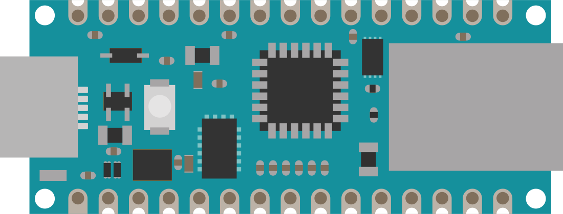
The Arduino 33 IoT is a powerful microcontroller board designed for Internet of Things (IoT) applications. It is based on the ESP32 microcontroller and features built-in Wi-Fi and Bluetooth connectivity, making it ideal for wireless communication and smart device integration. The board also includes a variety of onboard sensors, such as a temperature sensor and a 6-axis IMU (Inertial Measurement Unit), enabling advanced sensing capabilities. With full compatibility with the Arduino IDE, the Arduino 33 IoT is beginner-friendly while offering advanced features for experienced developers.
Explore Projects Built with Arduino 33 IOT

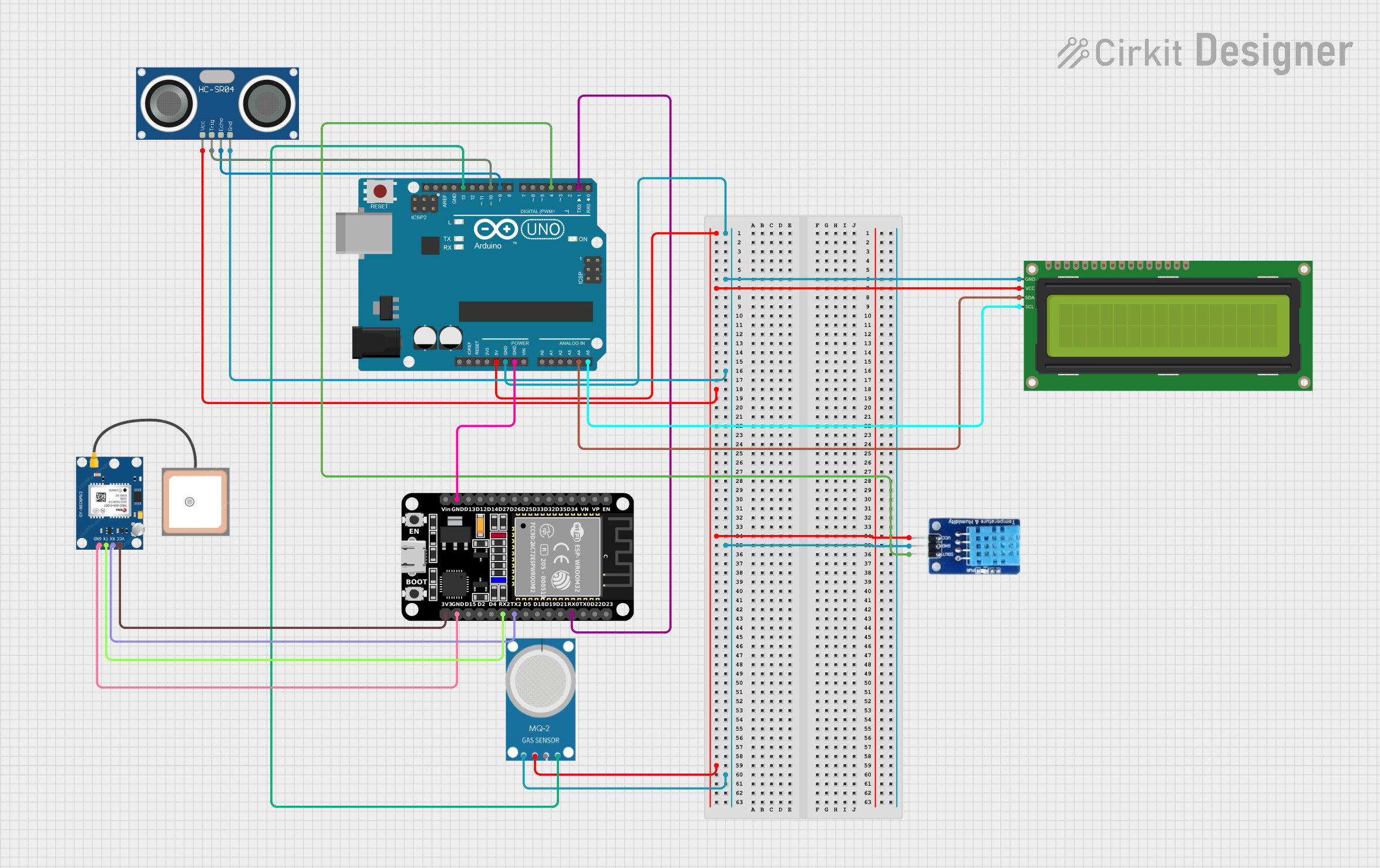
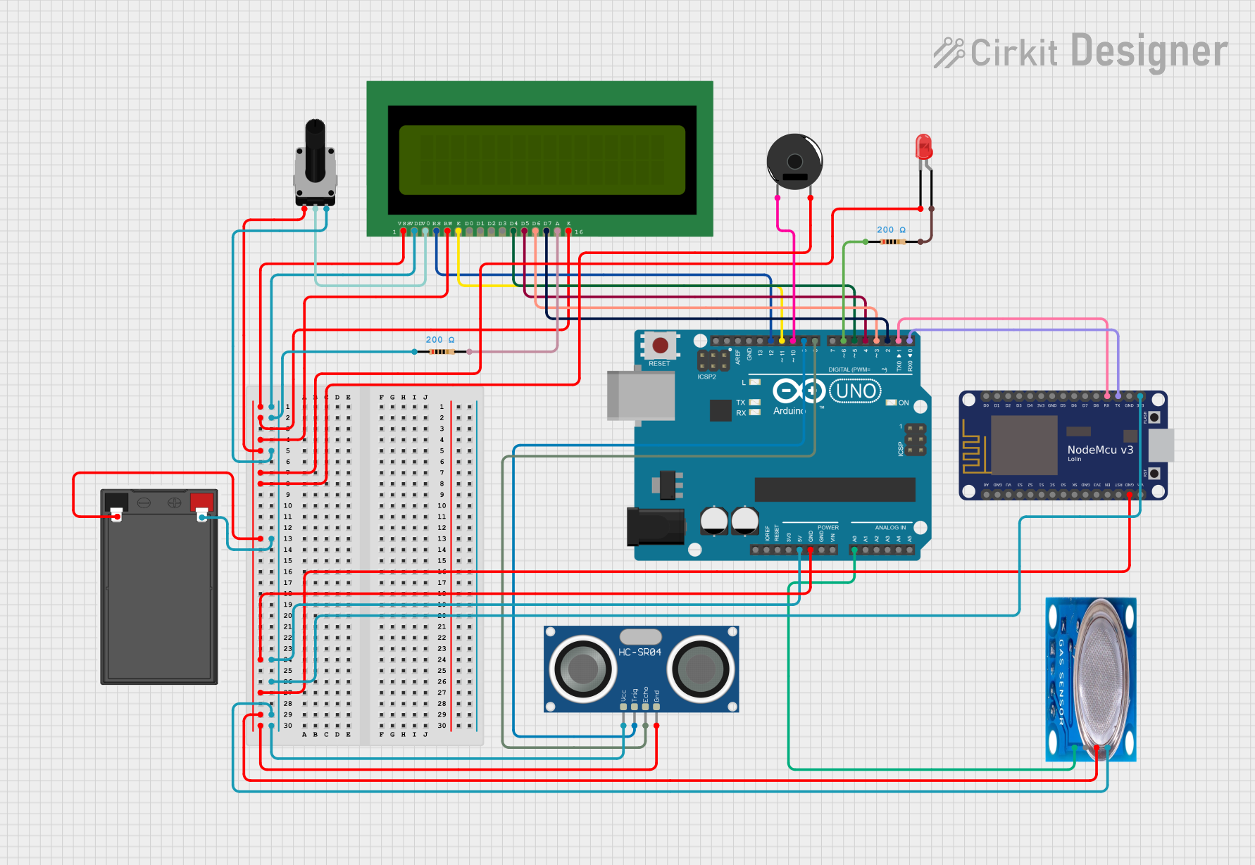
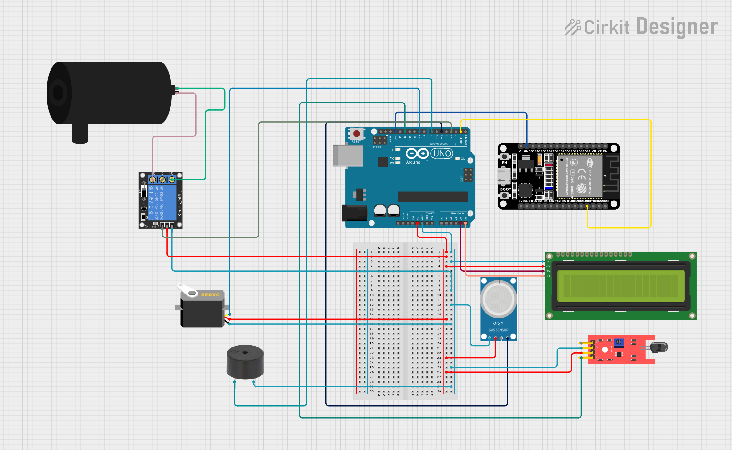
Explore Projects Built with Arduino 33 IOT
Common Applications and Use Cases
- Smart home automation systems
- Remote environmental monitoring
- Wearable devices
- Industrial IoT applications
- Wireless sensor networks
- Prototyping connected devices
Technical Specifications
Key Technical Details
- Microcontroller: ESP32
- Operating Voltage: 3.3V
- Input Voltage (recommended): 5V via USB or 7-12V via VIN pin
- Wi-Fi: IEEE 802.11 b/g/n
- Bluetooth: BLE (Bluetooth Low Energy) and Bluetooth Classic
- Flash Memory: 4MB
- SRAM: 520KB
- Clock Speed: 240 MHz
- Digital I/O Pins: 20
- PWM Pins: 16
- Analog Input Pins: 6 (12-bit ADC)
- Analog Output Pins: 1 (8-bit DAC)
- Communication Interfaces: UART, SPI, I2C
- Onboard Sensors: Temperature sensor, 6-axis IMU
- USB Interface: Micro USB
- Dimensions: 68.6mm x 25.4mm
Pin Configuration and Descriptions
The Arduino 33 IoT has a total of 20 digital I/O pins, which can be configured as input or output. Below is a table summarizing the pin configuration:
| Pin | Type | Description |
|---|---|---|
| VIN | Power Input | External power input (7-12V recommended). |
| 3.3V | Power Output | Provides 3.3V output for external components. |
| GND | Ground | Ground connection. |
| A0-A5 | Analog Input | 12-bit ADC pins for reading analog signals. |
| D0-D13 | Digital I/O | General-purpose digital input/output pins. |
| PWM | PWM Output | Pulse Width Modulation output available on most digital pins. |
| TX/RX | UART | Serial communication pins (TX for transmit, RX for receive). |
| SDA | I2C Data | Data line for I2C communication. |
| SCL | I2C Clock | Clock line for I2C communication. |
| SPI | SPI Interface | SPI communication pins (MOSI, MISO, SCK, SS). |
| DAC | Analog Output | 8-bit Digital-to-Analog Converter for generating analog signals. |
| IMU | Sensor Interface | Built-in 6-axis IMU for motion sensing. |
Usage Instructions
How to Use the Arduino 33 IoT in a Circuit
Powering the Board:
- Connect the board to your computer via a Micro USB cable for programming and power.
- Alternatively, supply power through the VIN pin (7-12V recommended).
Programming the Board:
- Install the Arduino IDE on your computer.
- Add the ESP32 board support package to the Arduino IDE via the Board Manager.
- Select "Arduino 33 IoT" from the Tools > Board menu.
- Write your code and upload it to the board using the USB connection.
Connecting Sensors and Actuators:
- Use the digital and analog pins to connect external components like sensors, LEDs, and motors.
- Ensure that the voltage and current requirements of connected components are compatible with the board.
Using Wi-Fi and Bluetooth:
- Use the built-in Wi-Fi and Bluetooth libraries in the Arduino IDE to enable wireless communication.
- For example, use the
WiFilibrary to connect to a network or theBLElibrary for Bluetooth communication.
Important Considerations and Best Practices
- Always use a level shifter when interfacing 5V components with the 3.3V pins of the Arduino 33 IoT.
- Avoid drawing excessive current from the 3.3V pin to prevent damage to the board.
- Use proper decoupling capacitors when connecting external sensors to reduce noise.
- Ensure that the board is placed in a well-ventilated area to prevent overheating during prolonged use.
Example Code for Arduino 33 IoT with Wi-Fi
Below is an example of how to connect the Arduino 33 IoT to a Wi-Fi network and print the IP address:
#include <WiFi.h> // Include the Wi-Fi library

const char* ssid = "Your_SSID";       // Replace with your Wi-Fi network name
const char* password = "Your_Password"; // Replace with your Wi-Fi password

void setup() {
  Serial.begin(115200); // Initialize serial communication
  delay(1000);

  Serial.println("Connecting to Wi-Fi...");
  WiFi.begin(ssid, password); // Start Wi-Fi connection

  while (WiFi.status() != WL_CONNECTED) {
    delay(500);
    Serial.print("."); // Print dots while connecting
  }

  Serial.println("\nWi-Fi connected!");
  Serial.print("IP Address: ");
  Serial.println(WiFi.localIP()); // Print the assigned IP address
}

void loop() {
  // Add your main code here
}
Troubleshooting and FAQs
Common Issues and Solutions
The board is not detected by the Arduino IDE:
- Ensure that the correct board ("Arduino 33 IoT") is selected in the Tools > Board menu.
- Check that the correct COM port is selected in the Tools > Port menu.
- Verify that the USB cable is functional and supports data transfer.
Wi-Fi connection fails:
- Double-check the SSID and password in your code.
- Ensure that the Wi-Fi network is within range and not restricted by MAC filtering.
The board overheats:
- Avoid drawing excessive current from the 3.3V pin.
- Ensure proper ventilation and avoid placing the board in enclosed spaces.
Bluetooth communication is unreliable:
- Check for interference from other Bluetooth devices.
- Ensure that the paired device is within the recommended range (typically 10 meters).
FAQs
Can I use the Arduino 33 IoT with 5V sensors?
No, the Arduino 33 IoT operates at 3.3V logic levels. Use a level shifter to interface with 5V sensors.What is the maximum range of the Wi-Fi module?
The range depends on environmental factors but is typically up to 30 meters indoors and 100 meters outdoors.Can I power the board with a battery?
Yes, you can use a 7-12V battery connected to the VIN pin.Is the Arduino 33 IoT compatible with Arduino shields?
Yes, it is compatible with most Arduino shields, but ensure that the shield operates at 3.3V logic levels.