How to Use RS232 to TTL Serial Port Module: Examples, Pinouts, and Specs
Introduction
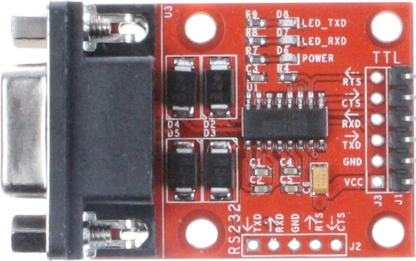
The RS232 to TTL Serial Port Module (Manufacturer: NOYITO, Part ID: NO-RS232TTL-335) is a compact and reliable module designed to convert RS232 serial communication signals to TTL (Transistor-Transistor Logic) levels. This conversion enables seamless communication between devices that operate on different voltage levels, such as microcontrollers, computers, and other serial devices.
Explore Projects Built with RS232 to TTL Serial Port Module


Explore Projects Built with RS232 to TTL Serial Port Module
Common Applications and Use Cases
- Interfacing microcontrollers (e.g., Arduino, Raspberry Pi) with RS232 devices.
- Connecting legacy RS232 equipment to modern TTL-based systems.
- Debugging and testing serial communication protocols.
- Data logging and communication in industrial automation systems.
Technical Specifications
The following are the key technical details of the NOYITO RS232 to TTL Serial Port Module:
| Parameter | Specification |
|---|---|
| Operating Voltage | 3.3V to 5V DC |
| RS232 Voltage Range | ±12V (standard RS232 levels) |
| TTL Voltage Levels | 0V (LOW) to 3.3V/5V (HIGH, depending on VCC input) |
| Baud Rate | Up to 115200 bps |
| Communication Protocol | Asynchronous Serial |
| Dimensions | 33mm x 14mm x 5mm |
| Operating Temperature | -40°C to +85°C |
Pin Configuration and Descriptions
The module features a 6-pin header for TTL communication and a DB9 connector for RS232 communication. Below is the pin configuration:
TTL Header Pinout
| Pin | Name | Description |
|---|---|---|
| 1 | VCC | Power input (3.3V or 5V DC) |
| 2 | GND | Ground connection |
| 3 | TXD | Transmit data (TTL level, output from the module) |
| 4 | RXD | Receive data (TTL level, input to the module) |
| 5 | RTS | Request to Send (optional, TTL level) |
| 6 | CTS | Clear to Send (optional, TTL level) |
DB9 Connector Pinout (RS232 Side)
| Pin | Name | Description |
|---|---|---|
| 2 | RXD | Receive data (RS232 level, input to the module) |
| 3 | TXD | Transmit data (RS232 level, output from the module) |
| 5 | GND | Ground connection |
| 7 | RTS | Request to Send (optional, RS232 level) |
| 8 | CTS | Clear to Send (optional, RS232 level) |
Usage Instructions
How to Use the Component in a Circuit
- Power the Module: Connect the VCC pin to a 3.3V or 5V DC power source, depending on the logic level of your TTL device. Connect the GND pin to the ground of your circuit.
- Connect TTL Device:
- Connect the TXD pin of the module to the RXD pin of your TTL device (e.g., microcontroller).
- Connect the RXD pin of the module to the TXD pin of your TTL device.
- Connect RS232 Device: Plug the DB9 connector into the RS232 device (e.g., a computer or industrial equipment).
- Optional Handshaking: If your application requires hardware flow control, connect the RTS and CTS pins on both the TTL and RS232 sides.
- Test Communication: Use a serial communication tool (e.g., Arduino Serial Monitor or a terminal emulator) to test data transmission between the devices.
Important Considerations and Best Practices
- Ensure that the VCC voltage matches the logic level of your TTL device (3.3V or 5V).
- Avoid connecting the module to RS232 devices that exceed the ±12V standard voltage range.
- Use short and shielded cables for RS232 connections to minimize noise and signal degradation.
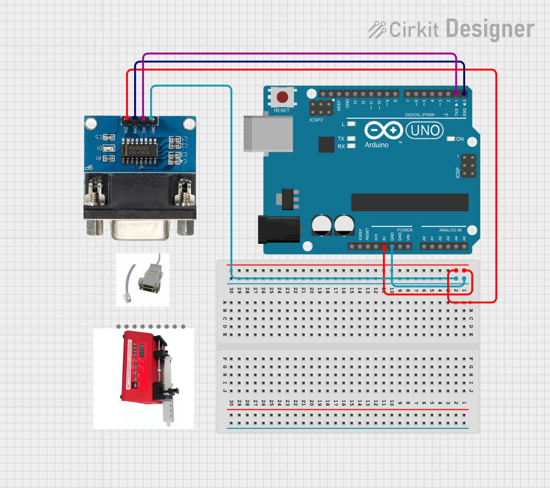
- If using with an Arduino UNO, connect the module's TXD pin to the Arduino's RX pin (D0) and the RXD pin to the Arduino's TX pin (D1).
Example Code for Arduino UNO
Below is an example code snippet to demonstrate communication between an Arduino UNO and an RS232 device using the module:
// Example: Arduino UNO communicating with an RS232 device via RS232 to TTL module

void setup() {
  Serial.begin(9600); // Initialize serial communication at 9600 baud
  Serial.println("RS232 to TTL Module Test"); // Send test message
}

void loop() {
  // Check if data is available from the RS232 device
  if (Serial.available() > 0) {
    char receivedChar = Serial.read(); // Read a character from RS232 device
    Serial.print("Received: ");
    Serial.println(receivedChar); // Print the received character
  }

  // Send a test message to the RS232 device every 2 seconds
  delay(2000);
  Serial.println("Hello from Arduino!");
}
Troubleshooting and FAQs
Common Issues and Solutions
No Communication Between Devices
- Cause: Incorrect wiring of TXD and RXD pins.
- Solution: Ensure TXD of the module is connected to RXD of the TTL device, and RXD of the module is connected to TXD of the TTL device.
Data Corruption or Noise
- Cause: Long or unshielded RS232 cables.
- Solution: Use shorter, shielded cables to reduce noise and signal degradation.
Module Not Powering On
- Cause: Incorrect VCC voltage or loose connections.
- Solution: Verify that the VCC pin is connected to a stable 3.3V or 5V power source and that the GND pin is properly connected.
Baud Rate Mismatch
- Cause: The RS232 and TTL devices are configured with different baud rates.
- Solution: Ensure both devices are set to the same baud rate (e.g., 9600 bps).
FAQs
Q1: Can this module be used with a Raspberry Pi?
A1: Yes, the module can be used with a Raspberry Pi. Ensure the VCC pin is connected to a 3.3V power source, as the Raspberry Pi operates at 3.3V logic levels.
Q2: Does the module support bidirectional communication?
A2: Yes, the module supports full-duplex communication, allowing simultaneous transmission and reception of data.
Q3: Can I use this module for RS485 communication?
A3: No, this module is specifically designed for RS232 to TTL conversion and does not support RS485 communication.
Q4: What is the maximum cable length for RS232 communication?
A4: The maximum cable length depends on the baud rate and cable quality. For standard RS232 communication, a length of up to 15 meters is typical at lower baud rates.