How to Use ESP32 NodeMCU Modul WiFi Entwicklungsboard mit CP2102: Examples, Pinouts, and Specs
Introduction
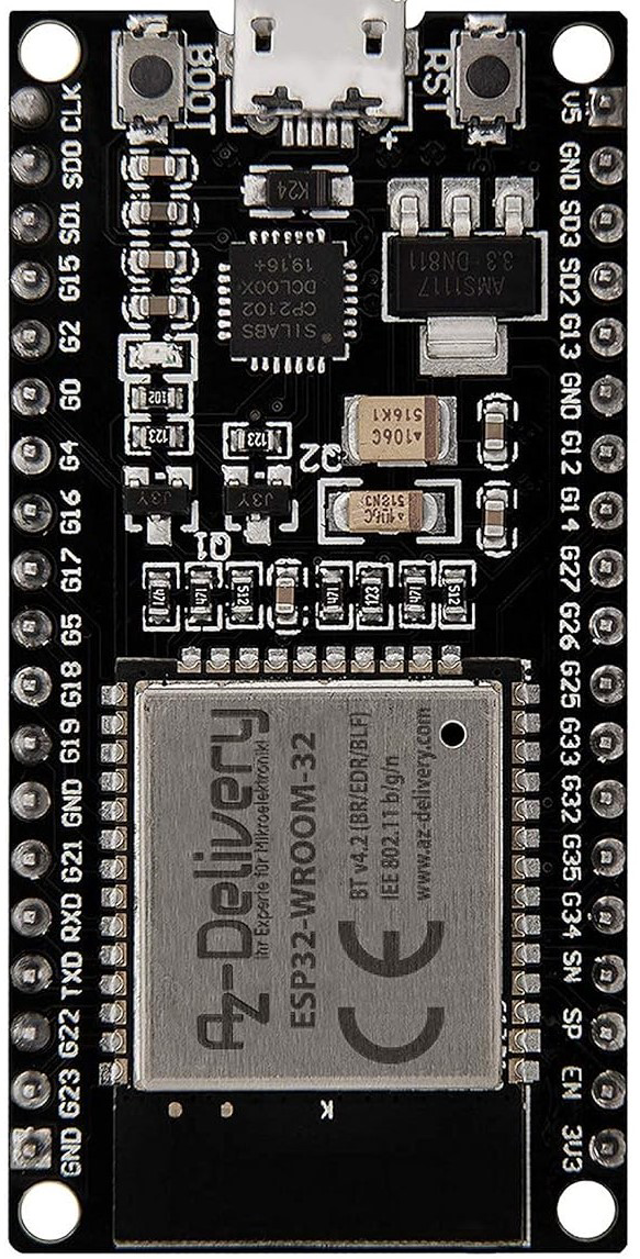
The ESP32 NodeMCU Modul WiFi Entwicklungsboard mit CP2102, manufactured by AZDelivery (Part ID: ESP32S Dev Kit C), is a powerful and versatile development board designed for Internet of Things (IoT) applications. It features the ESP32 chip, which integrates WiFi and Bluetooth capabilities, making it ideal for wireless communication projects. The board also includes a CP2102 USB-to-UART bridge, simplifying programming and serial communication with a computer.
Explore Projects Built with ESP32 NodeMCU Modul WiFi Entwicklungsboard mit CP2102


Explore Projects Built with ESP32 NodeMCU Modul WiFi Entwicklungsboard mit CP2102
Common Applications and Use Cases
- IoT devices and smart home automation
- Wireless sensor networks
- Remote data logging and monitoring
- Bluetooth-enabled applications
- Prototyping and development of WiFi/Bluetooth-based systems
Technical Specifications
The following table outlines the key technical details of the ESP32 NodeMCU Modul:
| Parameter | Specification |
|---|---|
| Microcontroller | ESP32 Dual-Core Xtensa LX6 |
| Clock Speed | Up to 240 MHz |
| Flash Memory | 4 MB (varies by model) |
| SRAM | 520 KB |
| WiFi | 802.11 b/g/n (2.4 GHz) |
| Bluetooth | Bluetooth 4.2 and BLE |
| Operating Voltage | 3.3 V |
| Input Voltage (via USB) | 5 V |
| GPIO Pins | 30 (multipurpose, including ADC, DAC, PWM, I2C, SPI) |
| USB-to-UART Bridge | CP2102 |
| Dimensions | 58 mm x 25.5 mm |
Pin Configuration and Descriptions
The ESP32 NodeMCU Modul has a total of 30 GPIO pins, which can be used for various purposes. Below is a table summarizing the key pins and their functions:
| Pin | Function | Description |
|---|---|---|
| VIN | Power Input | Connect to 5V input for powering the board. |
| 3V3 | 3.3V Output | Provides 3.3V output for external components. |
| GND | Ground | Common ground for the circuit. |
| EN | Enable | Active-high pin to enable the chip. |
| IO0 | GPIO0 / Boot Mode | Used for boot mode selection during programming. |
| IO2 | GPIO2 | General-purpose I/O pin. |
| IO4 | GPIO4 | General-purpose I/O pin. |
| IO5 | GPIO5 | General-purpose I/O pin. |
| IO12 | GPIO12 / ADC2_CH5 | Can be used as an analog input or digital I/O. |
| IO13 | GPIO13 / ADC2_CH4 | Can be used as an analog input or digital I/O. |
| IO14 | GPIO14 / ADC2_CH6 | Can be used as an analog input or digital I/O. |
| IO15 | GPIO15 / ADC2_CH3 | Can be used as an analog input or digital I/O. |
| IO16 | GPIO16 / UART2_RXD | Can be used as a UART receive pin or digital I/O. |
| IO17 | GPIO17 / UART2_TXD | Can be used as a UART transmit pin or digital I/O. |
| IO18 | GPIO18 / SPI_CLK | SPI clock pin or general-purpose I/O. |
| IO19 | GPIO19 / SPI_MISO | SPI MISO pin or general-purpose I/O. |
| IO21 | GPIO21 / I2C_SDA | I2C data pin or general-purpose I/O. |
| IO22 | GPIO22 / I2C_SCL | I2C clock pin or general-purpose I/O. |
| IO23 | GPIO23 / SPI_MOSI | SPI MOSI pin or general-purpose I/O. |
| IO25 | GPIO25 / DAC1 | Can be used as a DAC output or digital I/O. |
| IO26 | GPIO26 / DAC2 | Can be used as a DAC output or digital I/O. |
| IO27 | GPIO27 / ADC2_CH7 | Can be used as an analog input or digital I/O. |
| IO32 | GPIO32 / ADC1_CH4 | Can be used as an analog input or digital I/O. |
| IO33 | GPIO33 / ADC1_CH5 | Can be used as an analog input or digital I/O. |
| IO34 | GPIO34 / ADC1_CH6 (Input Only) | Analog input only. |
| IO35 | GPIO35 / ADC1_CH7 (Input Only) | Analog input only. |
Usage Instructions
How to Use the ESP32 NodeMCU Modul in a Circuit
Powering the Board:
- Connect the board to your computer using a micro-USB cable. This provides both power and a communication interface.
- Alternatively, supply 5V to the VIN pin and connect GND to the ground of your power source.
Programming the Board:
- Install the CP2102 USB-to-UART driver on your computer (if not already installed).
- Use the Arduino IDE or ESP-IDF (Espressif IoT Development Framework) to write and upload code to the board.
- Select the correct board type (
ESP32 Dev Module) and COM port in the Arduino IDE.
Connecting Peripherals:
- Use the GPIO pins to connect sensors, actuators, or other peripherals. Ensure that the voltage levels are compatible (3.3V logic).
Uploading Code:
- Press and hold the
BOOTbutton while uploading code to put the board in programming mode. - Release the
BOOTbutton once the upload begins.
- Press and hold the
Example: Blinking an LED with Arduino IDE
The following example demonstrates how to blink an LED connected to GPIO2:
// Define the GPIO pin where the LED is connected
const int ledPin = 2;

void setup() {
  // Set the LED pin as an output
  pinMode(ledPin, OUTPUT);
}

void loop() {
  // Turn the LED on
  digitalWrite(ledPin, HIGH);
  delay(1000); // Wait for 1 second

  // Turn the LED off
  digitalWrite(ledPin, LOW);
  delay(1000); // Wait for 1 second
}
Important Considerations and Best Practices
- Voltage Levels: Ensure that all connected peripherals operate at 3.3V logic levels to avoid damaging the board.
- Power Supply: If using power-hungry peripherals, consider using an external power source to avoid overloading the USB port.
- Boot Mode: Use the
BOOTbutton for programming mode if the board does not automatically enter it.
Troubleshooting and FAQs
Common Issues and Solutions
Problem: The board is not detected by the computer.
Solution:- Ensure the CP2102 driver is installed correctly.
- Try a different USB cable or port.
Problem: Code upload fails with a timeout error.
Solution:- Press and hold the
BOOTbutton while uploading the code. - Check that the correct COM port and board type are selected in the Arduino IDE.
- Press and hold the
Problem: The board resets unexpectedly during operation.
Solution:- Ensure the power supply is stable and sufficient.
- Avoid drawing excessive current from the GPIO pins.
FAQs
Q: Can I use 5V sensors with the ESP32?
A: Yes, but you will need a level shifter to convert 5V signals to 3.3V.Q: How do I enable deep sleep mode?
A: Use theesp_deep_sleep_start()function in your code. Connect GPIO16 to the RST pin for wake-up functionality.Q: Can I use the ESP32 with a battery?
A: Yes, connect a 3.7V LiPo battery to the VIN and GND pins. Use a voltage regulator if necessary.