
How to Use TRANSISTOR BD139 NEW: Examples, Pinouts, and Specs
 Design with TRANSISTOR BD139 NEW in Cirkit Designer
Introduction
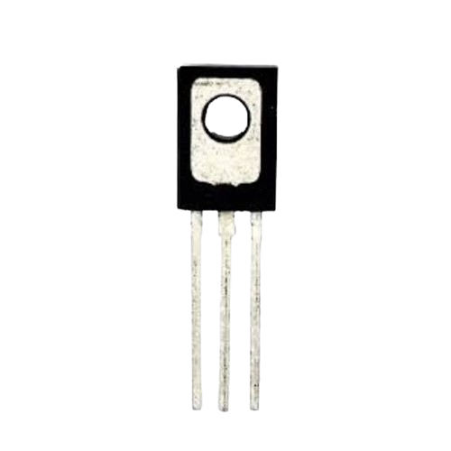
The BD139 is a general-purpose NPN transistor designed for switching and amplification tasks in electronic circuits. It is widely used due to its ability to handle moderate current and voltage levels, making it suitable for a variety of applications. The BD139 is commonly found in audio amplifiers, motor drivers, and other medium-power electronic devices.
Explore Projects Built with TRANSISTOR BD139 NEW
 Open Project in Cirkit Designer
 Open Project in Cirkit Designer
 Open Project in Cirkit Designer
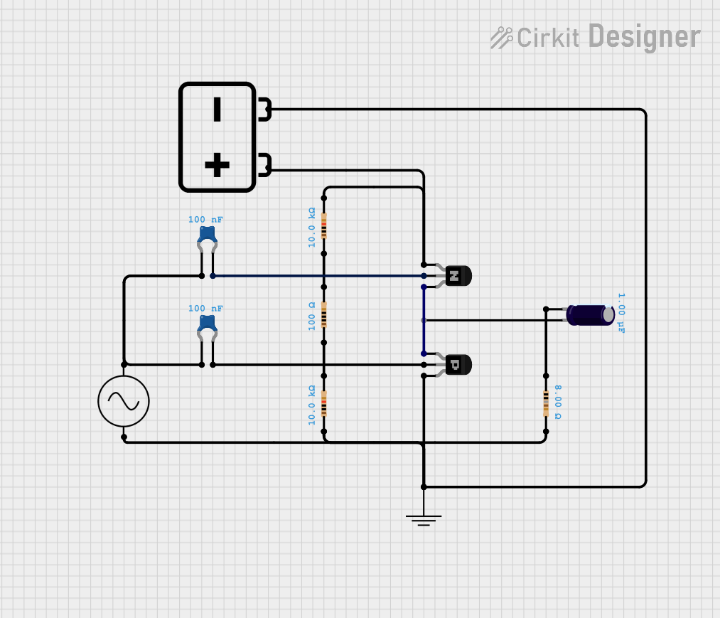 Open Project in Cirkit Designer
Explore Projects Built with TRANSISTOR BD139 NEW
Open Project in Cirkit DesignerOpen Project in Cirkit DesignerOpen Project in Cirkit DesignerOpen Project in Cirkit DesignerCommon Applications:
- Audio amplification
- Motor control circuits
- Signal switching
- Voltage regulation
- LED drivers
Technical Specifications
Below are the key technical details of the BD139 transistor:
| Parameter | Value |
|---|---|
| Transistor Type | NPN |
| Maximum Collector-Emitter Voltage (Vce) | 80V |
| Maximum Collector-Base Voltage (Vcb) | 100V |
| Maximum Emitter-Base Voltage (Veb) | 5V |
| Maximum Collector Current (Ic) | 1.5A |
| Maximum Power Dissipation (Pd) | 12.5W |
| DC Current Gain (hFE) | 25 to 250 |
| Transition Frequency (ft) | 190 MHz |
| Package Type | TO-126 |
Pin Configuration
The BD139 transistor has three pins: Base (B), Collector (C), and Emitter (E). The pinout is as follows:
| Pin Number | Pin Name | Description |
|---|---|---|
| 1 | Emitter (E) | Current flows out of this pin |
| 2 | Collector (C) | Current flows into this pin |
| 3 | Base (B) | Controls the transistor's operation |
The pin layout for the TO-126 package (front view, flat side facing you) is:
- Emitter
- Collector
- Base
Usage Instructions
Using the BD139 in a Circuit
The BD139 transistor can be used in both switching and amplification configurations. Below are the steps to use it effectively:
Determine the Configuration:
- For switching: Use the transistor as an electronic switch by applying a small current to the base to control a larger current between the collector and emitter.
- For amplification: Use the transistor to amplify weak signals by biasing it in the active region.
Base Resistor Selection:
- Always use a base resistor to limit the current flowing into the base pin. The value of the resistor can be calculated using Ohm's Law: [ R_b = \frac{V_{in} - V_{be}}{I_b} ] where ( V_{in} ) is the input voltage, ( V_{be} ) is the base-emitter voltage (typically 0.7V for BD139), and ( I_b ) is the desired base current.
Connect the Pins:
- Connect the emitter to ground (for NPN configuration).
- Connect the load between the collector and the positive supply voltage.
- Apply the input signal to the base through the base resistor.
Power Dissipation:
- Ensure the power dissipation does not exceed 12.5W. Use a heatsink if necessary to manage heat.
Example: Controlling an LED with Arduino UNO
Below is an example of using the BD139 transistor to control an LED with an Arduino UNO:
// Define the pin connected to the transistor's base
const int transistorBasePin = 9; // Pin 9 on Arduino

void setup() {
  pinMode(transistorBasePin, OUTPUT); // Set pin as output
}

void loop() {
  digitalWrite(transistorBasePin, HIGH); // Turn on the transistor
  delay(1000); // Keep LED on for 1 second
  digitalWrite(transistorBasePin, LOW);  // Turn off the transistor
  delay(1000); // Keep LED off for 1 second
}
Circuit Connections:
- Connect the emitter of the BD139 to ground.
- Connect the collector to one terminal of the LED (with a current-limiting resistor in series).
- Connect the other terminal of the LED to the positive supply voltage.
- Connect the base to Arduino pin 9 through a 1kΩ resistor.
Important Considerations:
- Avoid exceeding the maximum voltage and current ratings.
- Use a heatsink if the transistor operates at high power levels.
- Ensure proper biasing to avoid damaging the transistor.
Troubleshooting and FAQs
Common Issues and Solutions
Transistor Overheating:
- Cause: Exceeding the maximum power dissipation.
- Solution: Use a heatsink or reduce the load current.
No Output Signal:
- Cause: Incorrect pin connections or insufficient base current.
- Solution: Double-check the pin configuration and ensure the base resistor is correctly calculated.
Low Amplification:
- Cause: Operating outside the active region or low hFE.
- Solution: Adjust the biasing circuit to ensure the transistor operates in the active region.
LED Not Turning On:
- Cause: Incorrect base resistor value or insufficient base current.
- Solution: Recalculate the base resistor value and ensure the Arduino pin outputs a sufficient voltage.
FAQs
Q1: Can the BD139 be used for high-frequency applications?
A1: Yes, the BD139 has a transition frequency (( f_t )) of 190 MHz, making it suitable for moderate high-frequency applications.
Q2: What is the maximum load current the BD139 can handle?
A2: The BD139 can handle a maximum collector current (( I_c )) of 1.5A.
Q3: Can I use the BD139 without a heatsink?
A3: Yes, but only if the power dissipation is below 12.5W. For higher power levels, a heatsink is recommended.
Q4: Is the BD139 suitable for audio amplification?
A4: Yes, the BD139 is commonly used in audio amplifier circuits due to its good linearity and moderate power handling capabilities.