Cirkit Designer Logo
Cirkit Designer
Your all-in-one circuit design IDE
Home / 
Component Documentation

How to Use SparkFun LED Array - 8x7: Examples, Pinouts, and Specs

Image of SparkFun LED Array - 8x7
Cirkit Designer LogoDesign with SparkFun LED Array - 8x7 in Cirkit Designer

Introduction

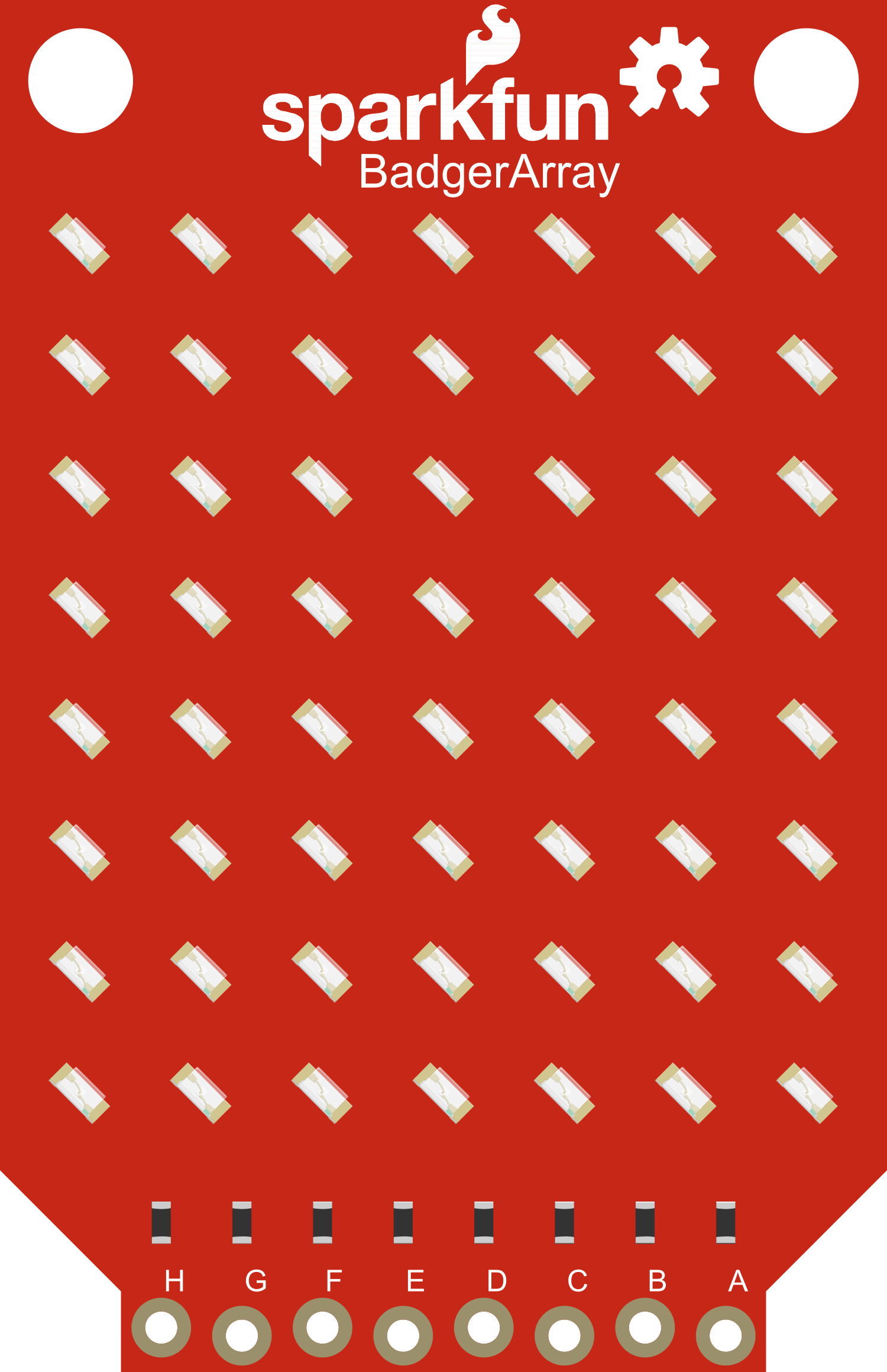
The SparkFun LED Array - 8x7 is a versatile and vibrant display module featuring 56 individually addressable RGB LEDs. This array allows users to create a wide range of colorful visual effects and patterns. It operates using the I2C communication protocol, making it simple to interface with microcontrollers such as the Arduino UNO. Common applications include custom indicators, gaming displays, message boards, and educational projects that require visual feedback.

Explore Projects Built with SparkFun LED Array - 8x7

Use Cirkit Designer to design, explore, and prototype these projects online. Some projects support real-time simulation. Click "Open Project" to start designing instantly!
Arduino UNO Controlled Multi-Matrix LED Display
Image of Test matrix with pixel moving: A project utilizing SparkFun LED Array - 8x7 in a practical application
This circuit consists of an Arduino UNO microcontroller connected to multiple MAX7219 8x8 LED Matrix modules arranged in a daisy-chain configuration. The Arduino controls the LED matrices using a software-implemented SPI communication protocol, with the purpose of displaying complex patterns or animations across the combined matrix display. The provided code handles the initialization and updating of the LED matrices, creating visual effects by manipulating the framebuffer and sending the data to the LED matrices in the correct order.
Cirkit Designer LogoOpen Project in Cirkit Designer
Arduino UNO Controlled Interactive Display with Joystick and Buzzer Feedback
Image of joystick: A project utilizing SparkFun LED Array - 8x7 in a practical application
This circuit features an Arduino UNO microcontroller connected to an 8x8 LED matrix, an LCD display with I2C interface, a KY-023 Dual Axis Joystick Module, and a Piezo Buzzer. The Arduino controls the LED matrix via digital pins and provides an interface for the joystick's analog inputs and button press. The LCD display is used for output, and the buzzer is driven by a digital pin for audio feedback.
Cirkit Designer LogoOpen Project in Cirkit Designer
Arduino UNO Controlled LED Matrix and LCD Interface with Joystick Interaction
Image of Digital Game Circuit: A project utilizing SparkFun LED Array - 8x7 in a practical application
This circuit features an Arduino UNO microcontroller interfaced with an 8x8 LED matrix, an LCD screen, and a KY-023 Dual Axis Joystick Module. The Arduino controls the LED matrix via digital pins D10-D12 and powers the matrix, LCD, and joystick module from its 5V output. The joystick's analog outputs are connected to the Arduino's analog inputs A0 and A1 for position sensing, while the LCD is controlled through digital pins D2-D6 and D13 for display purposes.
Cirkit Designer LogoOpen Project in Cirkit Designer
Arduino UNO-Based Interactive LED Game with 8x8 Matrix and TM1637 Display
Image of Gra_na_refleks: A project utilizing SparkFun LED Array - 8x7 in a practical application
This circuit is a game system controlled by an Arduino UNO, featuring an 8x8 LED matrix, a 4x4 keypad, and a TM1637 4-digit display. The user interacts with the game via the keypad, and the game state is displayed on the LED matrix and the TM1637 display, with power supplied by a 9V battery.
Cirkit Designer LogoOpen Project in Cirkit Designer

Explore Projects Built with SparkFun LED Array - 8x7

Use Cirkit Designer to design, explore, and prototype these projects online. Some projects support real-time simulation. Click "Open Project" to start designing instantly!
Image of Test matrix with pixel moving: A project utilizing SparkFun LED Array - 8x7 in a practical application
Arduino UNO Controlled Multi-Matrix LED Display
This circuit consists of an Arduino UNO microcontroller connected to multiple MAX7219 8x8 LED Matrix modules arranged in a daisy-chain configuration. The Arduino controls the LED matrices using a software-implemented SPI communication protocol, with the purpose of displaying complex patterns or animations across the combined matrix display. The provided code handles the initialization and updating of the LED matrices, creating visual effects by manipulating the framebuffer and sending the data to the LED matrices in the correct order.
Cirkit Designer LogoOpen Project in Cirkit Designer
Image of joystick: A project utilizing SparkFun LED Array - 8x7 in a practical application
Arduino UNO Controlled Interactive Display with Joystick and Buzzer Feedback
This circuit features an Arduino UNO microcontroller connected to an 8x8 LED matrix, an LCD display with I2C interface, a KY-023 Dual Axis Joystick Module, and a Piezo Buzzer. The Arduino controls the LED matrix via digital pins and provides an interface for the joystick's analog inputs and button press. The LCD display is used for output, and the buzzer is driven by a digital pin for audio feedback.
Cirkit Designer LogoOpen Project in Cirkit Designer
Image of Digital Game Circuit: A project utilizing SparkFun LED Array - 8x7 in a practical application
Arduino UNO Controlled LED Matrix and LCD Interface with Joystick Interaction
This circuit features an Arduino UNO microcontroller interfaced with an 8x8 LED matrix, an LCD screen, and a KY-023 Dual Axis Joystick Module. The Arduino controls the LED matrix via digital pins D10-D12 and powers the matrix, LCD, and joystick module from its 5V output. The joystick's analog outputs are connected to the Arduino's analog inputs A0 and A1 for position sensing, while the LCD is controlled through digital pins D2-D6 and D13 for display purposes.
Cirkit Designer LogoOpen Project in Cirkit Designer
Image of Gra_na_refleks: A project utilizing SparkFun LED Array - 8x7 in a practical application
Arduino UNO-Based Interactive LED Game with 8x8 Matrix and TM1637 Display
This circuit is a game system controlled by an Arduino UNO, featuring an 8x8 LED matrix, a 4x4 keypad, and a TM1637 4-digit display. The user interacts with the game via the keypad, and the game state is displayed on the LED matrix and the TM1637 display, with power supplied by a 9V battery.
Cirkit Designer LogoOpen Project in Cirkit Designer

Technical Specifications

Key Technical Details

  • Operating Voltage: 3.3V to 5V
  • Communication: I2C protocol
  • LED Count: 56 (8x7 matrix)
  • Color Depth: 24-bit color (RGB)
  • Default I2C Address: 0x77 (can be changed)
  • Dimensions: 60mm x 60mm

Pin Configuration and Descriptions

Pin Name Description
VCC Power supply (3.3V to 5V)
GND Ground
SDA I2C Data line
SCL I2C Clock line
INT Interrupt (optional use)

Usage Instructions

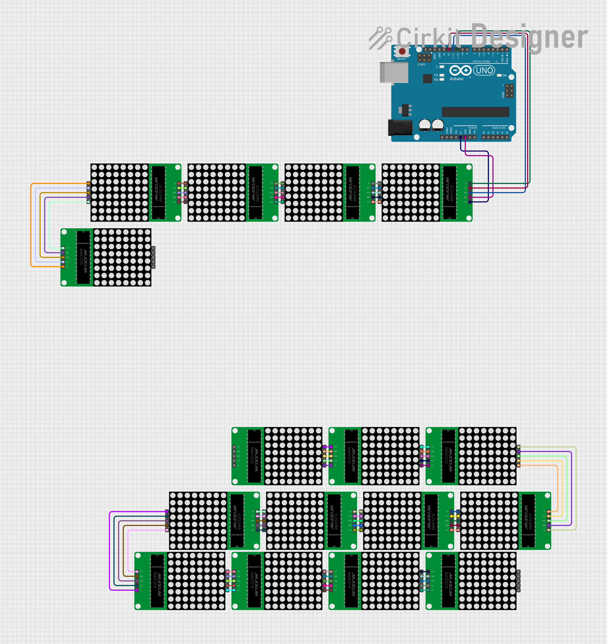
Interfacing with Arduino

To use the SparkFun LED Array with an Arduino UNO, follow these steps:

  1. Connect the LED Array to the Arduino:

    • VCC to 5V
    • GND to GND
    • SDA to A4 (or the SDA pin if using a different Arduino model)
    • SCL to A5 (or the SCL pin if using a different Arduino model)
  2. Install the Required Library:

    • Download and install the SparkFun LED Array library from the Arduino Library Manager or SparkFun's GitHub repository.
  3. Programming the Arduino:

    • Open the Arduino IDE and include the SparkFun LED Array library.
    • Initialize the LED array and set the I2C address if necessary.
    • Use the library functions to control individual LEDs or create patterns.

Example Code

#include <SparkFun_LED_Array.h> // Include the SparkFun LED Array library

SparkFun_LED_Array ledArray; // Create an LED Array object

void setup() {
  Wire.begin(); // Initialize I2C communication
  ledArray.begin(); // Initialize the LED Array
}

void loop() {
  // Example: Set the first LED to red
  ledArray.setLEDColor(0, 255, 0, 0); // Set LED at index 0 to red
  ledArray.updateDisplay(); // Update the display to show changes
  delay(500); // Wait for 500 milliseconds

  // Turn off the first LED
  ledArray.setLEDColor(0, 0, 0, 0); // Set LED at index 0 to off
  ledArray.updateDisplay(); // Update the display to show changes
  delay(500); // Wait for 500 milliseconds
}

Important Considerations and Best Practices

  • Ensure the power supply voltage does not exceed the recommended range to prevent damage to the LED array.
  • When addressing individual LEDs, remember that the index starts at 0 and ends at 55.
  • To prevent flickering, use updateDisplay() after setting the desired LED colors.
  • For complex patterns, it's recommended to calculate the entire frame before calling updateDisplay() to ensure smooth transitions.

Troubleshooting and FAQs

Common Issues

  • LEDs Not Lighting Up:

    • Check the wiring and ensure proper connections to the Arduino.
    • Verify that the power supply is within the operating voltage range.
    • Ensure that the I2C address is correctly set in the code if it has been changed from the default.
  • Flickering LEDs:

    • Minimize the number of times updateDisplay() is called in quick succession.
    • Ensure that the power supply is stable and can provide sufficient current.
  • Incorrect Colors Displayed:

    • Confirm that the color values are correctly set in the code.
    • Check for any issues with the I2C communication.

FAQs

  • Q: Can I change the I2C address of the LED array?

    • A: Yes, the I2C address can be changed to avoid conflicts with other I2C devices.
  • Q: How many LED arrays can I chain together?

    • A: You can chain multiple arrays as long as unique I2C addresses are assigned to each and the power supply can handle the current draw.
  • Q: Is it possible to use this LED array with other microcontrollers?

    • A: Absolutely, any microcontroller with I2C capability can be used to control the LED array.

For further assistance, consult the SparkFun LED Array - 8x7 forums and community resources.