How to Use Watt Meter DC: Examples, Pinouts, and Specs
Introduction
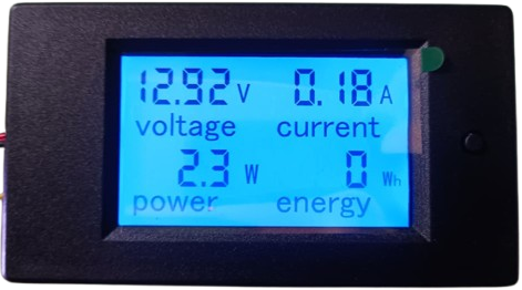
A Watt Meter DC is a device used to measure the electrical power (in watts) consumed by a DC circuit. It provides real-time readings of voltage, current, and power, enabling users to assess energy usage and efficiency. This component is widely used in applications such as solar power systems, battery monitoring, electric vehicles, and other DC-powered devices. Its ability to provide accurate power measurements makes it an essential tool for engineers, hobbyists, and energy-conscious users.
Explore Projects Built with Watt Meter DC
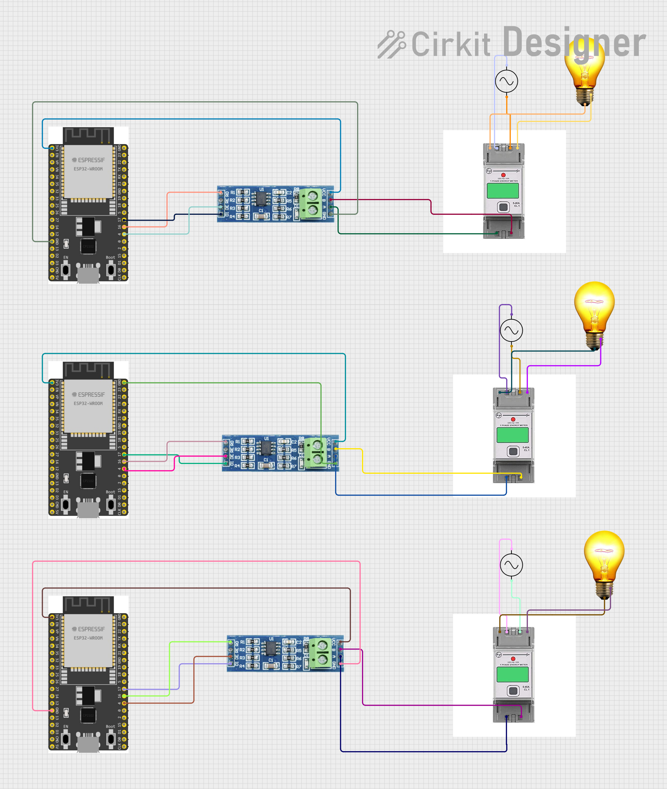
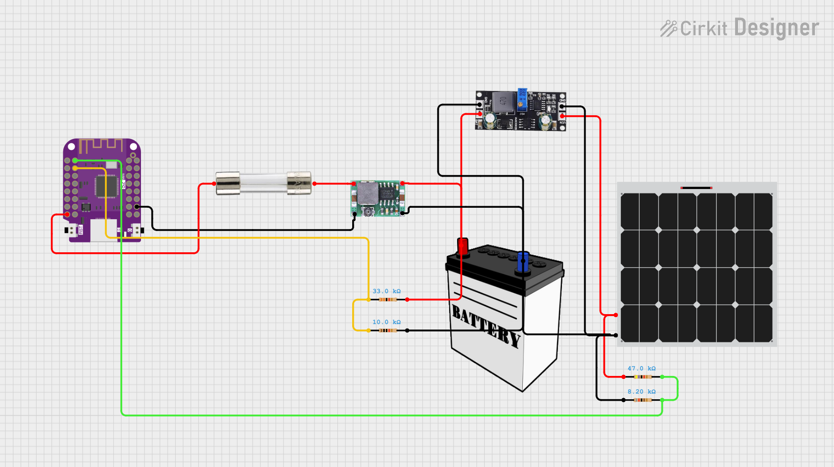
Explore Projects Built with Watt Meter DC
Technical Specifications
Below are the key technical details of a typical Watt Meter DC:
- Voltage Range: 0V to 60V DC
- Current Range: 0A to 100A DC (varies by model)
- Power Range: 0W to 6000W
- Accuracy: ±1% (varies by manufacturer)
- Display: LCD or LED (shows voltage, current, and power)
- Operating Temperature: -10°C to 60°C
- Power Consumption: Typically < 10mA
- Input/Output Ports: Screw terminals or XT60 connectors (varies by model)
Pin Configuration and Descriptions
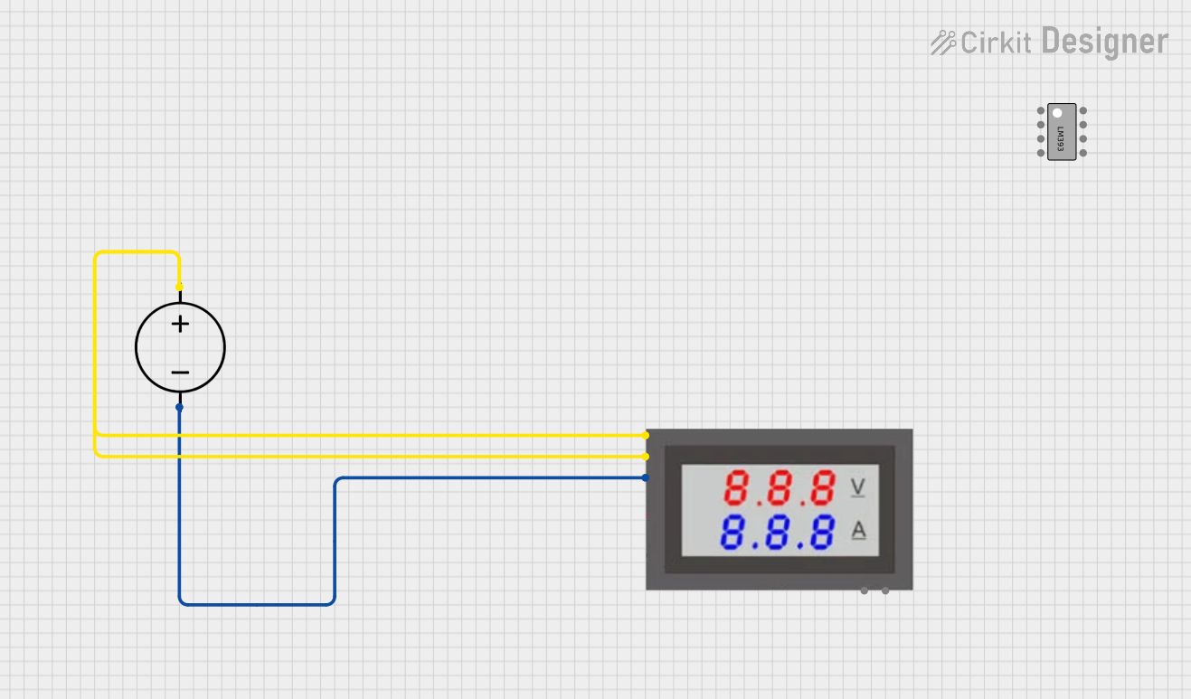
The Watt Meter DC typically has four connection points: two for the input (power source) and two for the output (load). Below is a table describing these connections:
| Pin/Terminal | Label | Description |
|---|---|---|
| 1 | + Input |
Positive terminal for the DC power source (e.g., battery or power supply). |
| 2 | - Input |
Negative terminal for the DC power source. |
| 3 | + Output |
Positive terminal for the load (e.g., motor, light, or other DC device). |
| 4 | - Output |
Negative terminal for the load. |
Note: Always ensure correct polarity when connecting the Watt Meter DC to avoid damage to the device or circuit.
Usage Instructions
How to Use the Watt Meter DC in a Circuit
Connect the Input Terminals:
- Connect the
+ Inputterminal to the positive terminal of the DC power source. - Connect the
- Inputterminal to the negative terminal of the DC power source.
- Connect the
Connect the Output Terminals:
- Connect the
+ Outputterminal to the positive terminal of the load. - Connect the
- Outputterminal to the negative terminal of the load.
- Connect the
Power On the Circuit:
- Once all connections are secure, power on the DC power source. The Watt Meter DC will display real-time readings of voltage, current, and power.
Monitor the Readings:
- Use the displayed values to monitor the power consumption of the load. This information can help optimize energy usage and identify inefficiencies.
Important Considerations and Best Practices
- Polarity: Always double-check the polarity of the connections. Reversing the polarity can damage the Watt Meter DC.
- Current Rating: Ensure the load's current does not exceed the maximum current rating of the Watt Meter DC.
- Heat Dissipation: For high-current applications, ensure proper ventilation or cooling to prevent overheating.
- Calibration: Some models may require calibration for accurate readings. Refer to the manufacturer's instructions for calibration procedures.
- Arduino Integration: If you wish to log data or automate measurements, you can connect the Watt Meter DC to an Arduino using additional sensors or modules.
Example Arduino Code for Monitoring Power
If you are using a current and voltage sensor (e.g., INA219) with an Arduino to replicate the functionality of a Watt Meter DC, here is an example code snippet:
#include <Wire.h>
#include <Adafruit_INA219.h>

// Create an INA219 instance
Adafruit_INA219 ina219;

void setup() {
  Serial.begin(9600); // Initialize serial communication at 9600 baud
  if (!ina219.begin()) {
    Serial.println("Failed to find INA219 chip"); // Error if sensor is not detected
    while (1); // Halt execution
  }
  Serial.println("INA219 initialized successfully");
}

void loop() {
  float voltage = ina219.getBusVoltage_V(); // Get bus voltage in volts
  float current = ina219.getCurrent_mA() / 1000.0; // Get current in amps
  float power = voltage * current; // Calculate power in watts

  // Print the readings to the Serial Monitor
  Serial.print("Voltage: ");
  Serial.print(voltage);
  Serial.print(" V, Current: ");
  Serial.print(current);
  Serial.print(" A, Power: ");
  Serial.print(power);
  Serial.println(" W");

  delay(1000); // Wait 1 second before the next reading
}
Note: The above code uses the Adafruit INA219 library to measure voltage and current. Ensure you have the library installed in your Arduino IDE.
Troubleshooting and FAQs
Common Issues and Solutions
No Display or Readings:
- Cause: Incorrect wiring or no power supply.
- Solution: Verify all connections and ensure the power source is functioning.
Inaccurate Readings:
- Cause: Calibration issue or exceeding the device's rated range.
- Solution: Recalibrate the device if possible, and ensure the load is within the specified range.
Device Overheating:
- Cause: High current exceeding the device's capacity.
- Solution: Reduce the load or use a Watt Meter DC with a higher current rating.
Polarity Reversal:
- Cause: Input and output terminals are connected incorrectly.
- Solution: Disconnect immediately and reconnect with the correct polarity.
FAQs
Q1: Can the Watt Meter DC measure AC power?
No, the Watt Meter DC is designed specifically for DC circuits. For AC power measurements, use an AC watt meter.
Q2: Can I use the Watt Meter DC with an Arduino?
Yes, but the Watt Meter DC itself does not have direct Arduino compatibility. You can use sensors like INA219 to measure voltage and current and calculate power programmatically.
Q3: What happens if I exceed the maximum current rating?
Exceeding the current rating can damage the Watt Meter DC or cause it to overheat. Always ensure the load is within the specified range.
Q4: How do I know if the device is calibrated?
Most Watt Meters DC are pre-calibrated. If you suspect inaccuracies, refer to the manufacturer's manual for calibration instructions.