How to Use Pushbutton: Examples, Pinouts, and Specs
Introduction
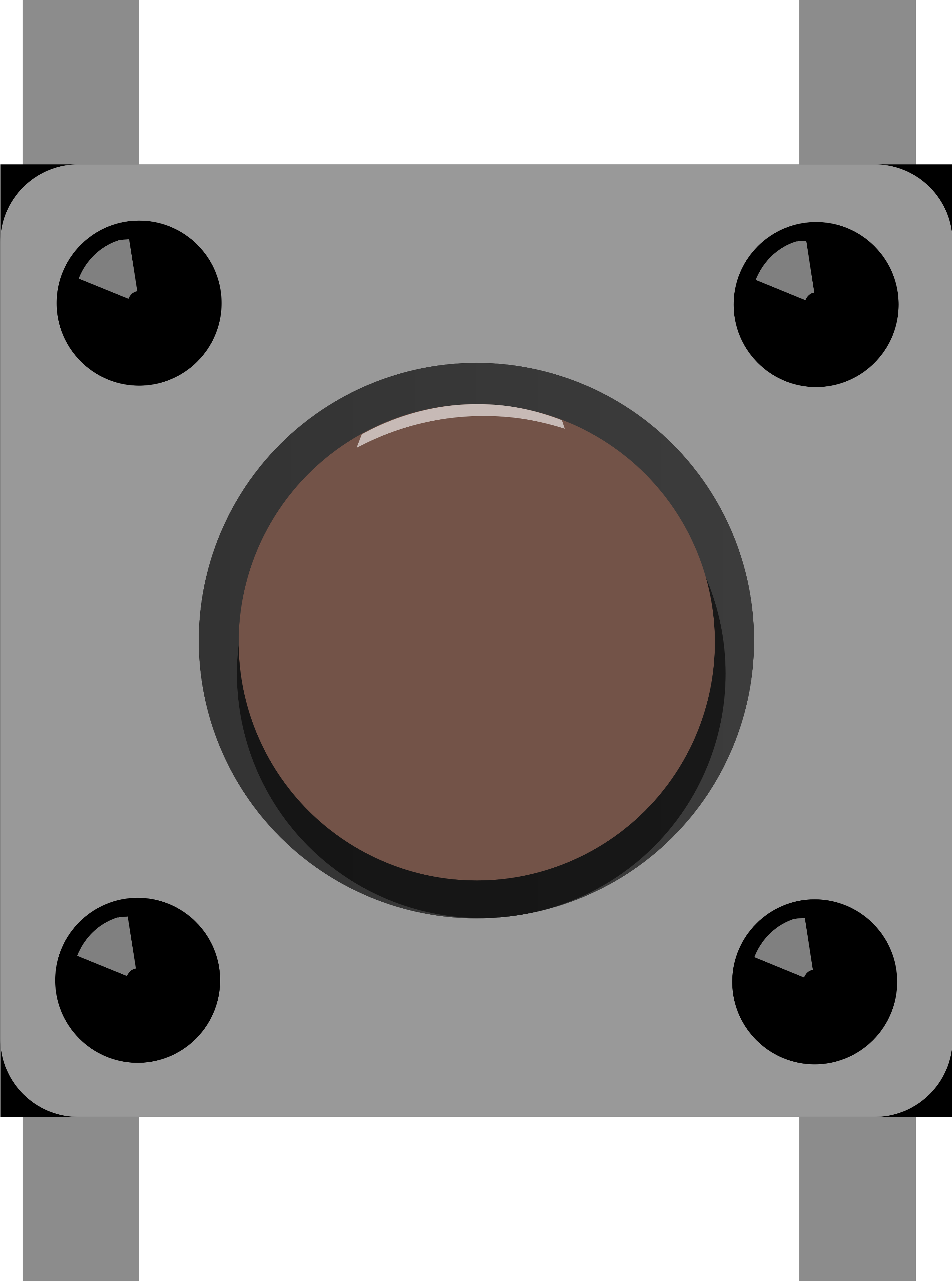
A pushbutton is a momentary switch that completes a circuit when pressed and breaks the circuit when released. It is a simple yet essential component in electronics, commonly used for user input in devices such as calculators, remote controls, and microcontroller-based projects. Pushbuttons are available in various sizes and designs, making them versatile for a wide range of applications.
Explore Projects Built with Pushbutton


Explore Projects Built with Pushbutton
Common Applications and Use Cases
- User input for microcontroller projects (e.g., Arduino, Raspberry Pi)
- Reset or power buttons in electronic devices
- Control panels for appliances and machinery
- Prototyping and testing circuits
- Interactive projects such as games or toys
Technical Specifications
Below are the general technical specifications for a standard pushbutton:
| Parameter | Value |
|---|---|
| Operating Voltage | 3.3V to 12V (typical) |
| Maximum Current Rating | 50mA to 500mA (depending on type) |
| Contact Resistance | ≤ 100 mΩ |
| Insulation Resistance | ≥ 100 MΩ |
| Operating Temperature | -20°C to +70°C |
| Actuation Force | 100g to 300g (varies by model) |
| Lifespan | 100,000 to 1,000,000 cycles |
Pin Configuration and Descriptions
A standard pushbutton typically has four pins, though only two are functionally required. The additional two pins are duplicates for mechanical stability and ease of connection.
| Pin Number | Description |
|---|---|
| Pin 1 | Normally open (NO) terminal |
| Pin 2 | Normally open (NO) terminal (duplicate) |
| Pin 3 | Ground (GND) terminal |
| Pin 4 | Ground (GND) terminal (duplicate) |
Note: Pins 1 and 2 are internally connected, as are Pins 3 and 4. You can use either pair for your circuit.
Usage Instructions
How to Use the Pushbutton in a Circuit
Connect the Pushbutton:
- Connect one side of the pushbutton (e.g., Pin 1 or Pin 2) to the input voltage (VCC).
- Connect the other side (e.g., Pin 3 or Pin 4) to the input pin of your microcontroller or circuit.
- Use a pull-down resistor (typically 10kΩ) between the input pin and ground to ensure a stable LOW signal when the button is not pressed.
Debounce the Signal:
- Pushbuttons can produce noise or "bouncing" when pressed or released. Use a capacitor (e.g., 0.1µF) in parallel with the button or implement software debouncing in your code.
Test the Circuit:
- Verify the button's functionality by observing the output signal when pressed and released.
Important Considerations and Best Practices
- Always use a pull-up or pull-down resistor to avoid floating input signals.
- Avoid exceeding the voltage and current ratings to prevent damage.
- For long-term reliability, choose a pushbutton with a lifespan suitable for your application.
- If using in a noisy environment, consider additional filtering components to reduce interference.
Example: Connecting a Pushbutton to an Arduino UNO
Below is an example of how to connect and use a pushbutton with an Arduino UNO:
Circuit Diagram
- Connect one terminal of the pushbutton to digital pin 2 on the Arduino.
- Connect the other terminal to ground (GND).
- Add a 10kΩ pull-up resistor between digital pin 2 and 5V.
Arduino Code
// Define the pin connected to the pushbutton
const int buttonPin = 2;

// Variable to store the button state
int buttonState = 0;

void setup() {
  // Set the button pin as input
  pinMode(buttonPin, INPUT);

  // Initialize serial communication for debugging
  Serial.begin(9600);
}

void loop() {
  // Read the state of the pushbutton
  buttonState = digitalRead(buttonPin);

  // Print the button state to the Serial Monitor
  if (buttonState == HIGH) {
    Serial.println("Button Pressed");
  } else {
    Serial.println("Button Released");
  }

  // Add a small delay to avoid spamming the Serial Monitor
  delay(100);
}
Troubleshooting and FAQs
Common Issues and Solutions
Button Not Responding:
- Cause: Loose connections or incorrect wiring.
- Solution: Double-check the wiring and ensure all connections are secure.
Button Produces Erratic Behavior:
- Cause: Signal bouncing due to mechanical contacts.
- Solution: Add a capacitor for hardware debouncing or implement software debouncing in your code.
Microcontroller Reads Incorrect States:
- Cause: Floating input pin.
- Solution: Use a pull-up or pull-down resistor to stabilize the signal.
Button Wears Out Quickly:
- Cause: Exceeding the rated lifespan or using a low-quality button.
- Solution: Choose a pushbutton with a higher lifespan rating for frequent use.
FAQs
Q: Can I use a pushbutton without a resistor?
A: While it is possible, it is not recommended. Without a pull-up or pull-down resistor, the input pin may float, leading to unreliable readings.
Q: How do I debounce a pushbutton in software?
A: You can use a delay after detecting a button press or implement a state-change detection algorithm to filter out noise.
Q: Can I use a pushbutton with higher voltages?
A: Only if the pushbutton's voltage and current ratings support it. Otherwise, use a relay or transistor to handle higher voltages.
Q: What is the difference between a pushbutton and a toggle switch?
A: A pushbutton is momentary (only active while pressed), whereas a toggle switch maintains its state until toggled again.