How to Use Motor Speed Controller: Examples, Pinouts, and Specs
Introduction
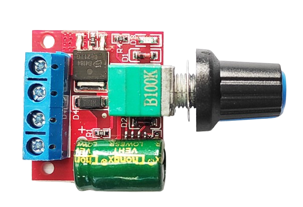
A Motor Speed Controller is a device used to regulate the speed of an electric motor by adjusting the voltage or current supplied to it. This component is essential in applications where precise motor speed control is required, such as in robotics, conveyor belts, electric vehicles, and industrial machinery. By varying the power delivered to the motor, the controller allows for smooth acceleration, deceleration, and speed stabilization.
Common applications and use cases:
- Robotics and automation systems
- Electric vehicles and drones
- Industrial machinery and conveyor systems
- HVAC systems (fans and pumps)
- Home appliances (e.g., washing machines, power tools)
Explore Projects Built with Motor Speed Controller

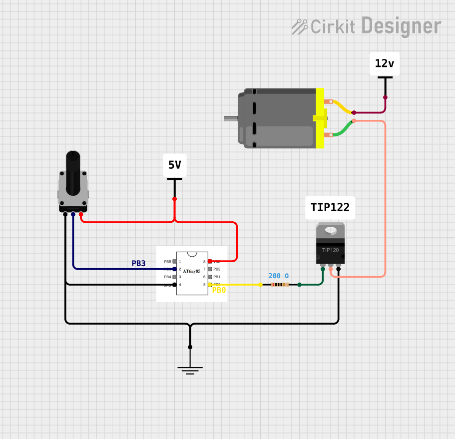
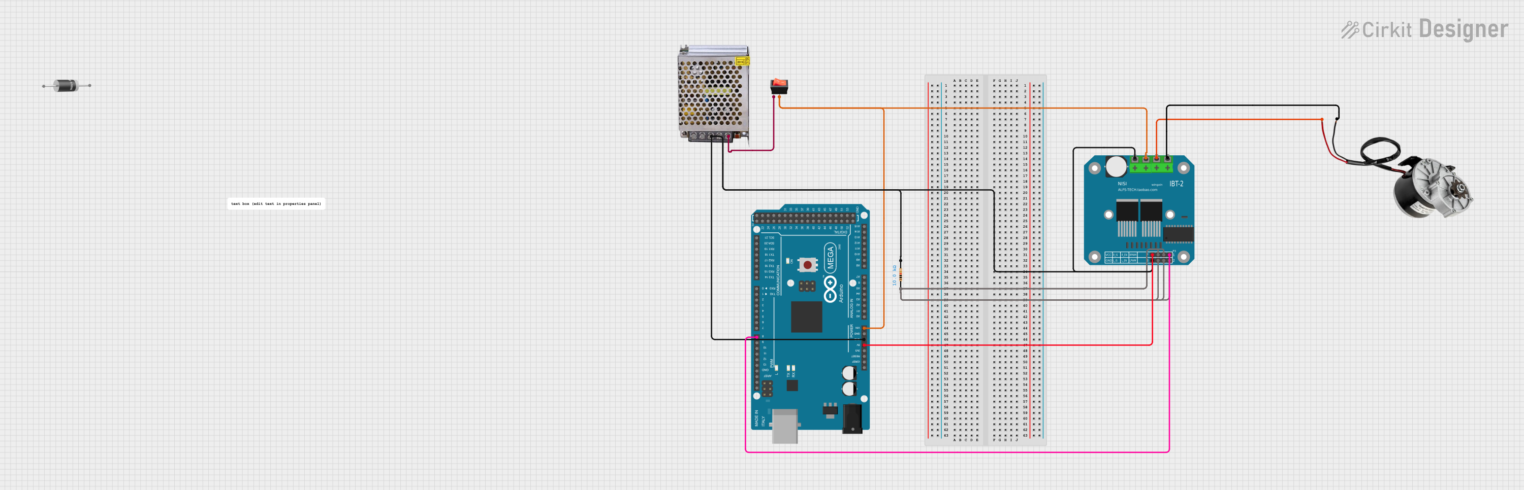
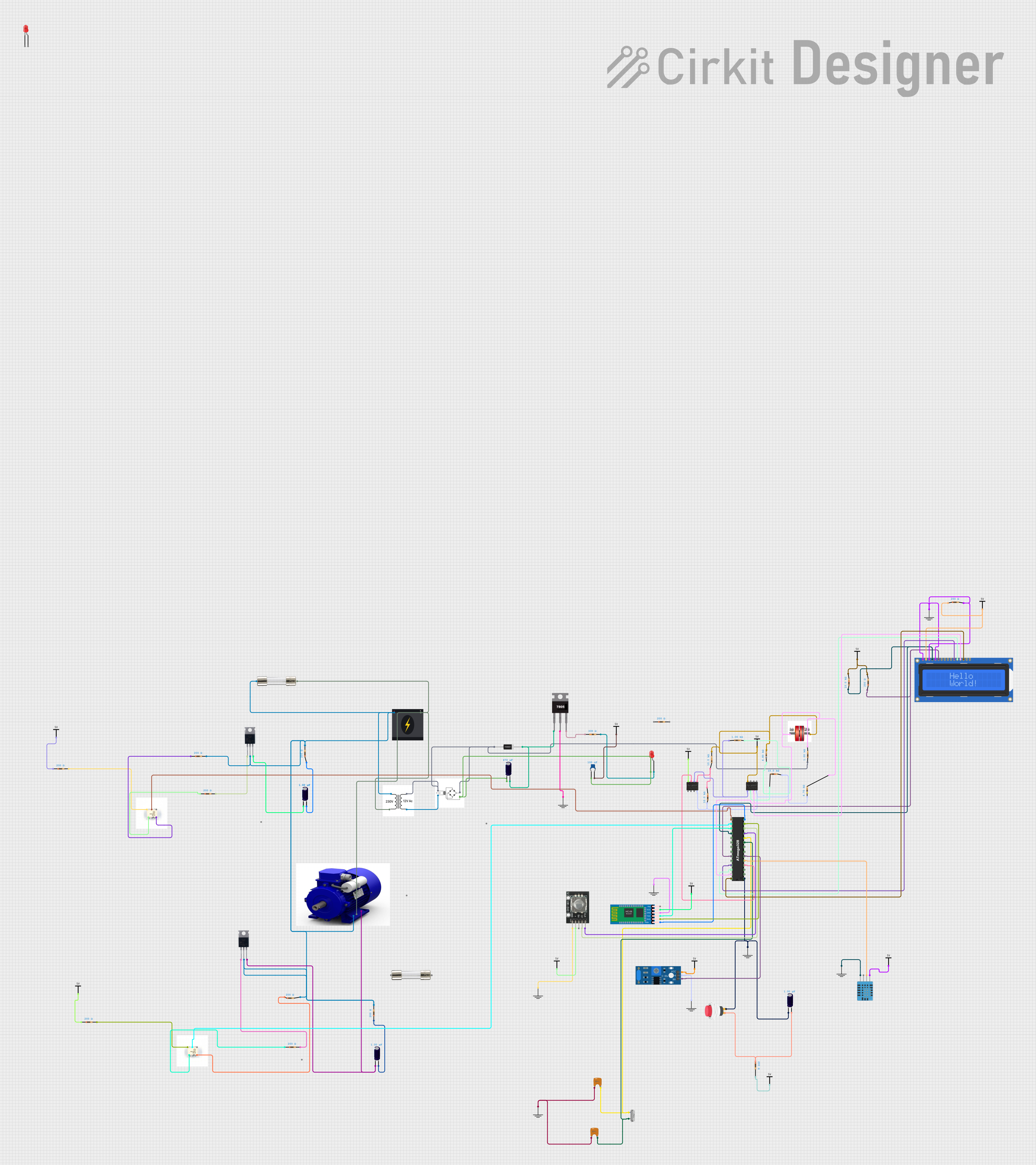
Explore Projects Built with Motor Speed Controller
Technical Specifications
Below are the general technical specifications for a typical Motor Speed Controller. Note that specific models may vary, so always refer to the datasheet of your specific controller.
| Parameter | Value |
|---|---|
| Input Voltage Range | 6V to 30V DC |
| Output Current | Up to 10A (depending on the model) |
| Control Signal | PWM (Pulse Width Modulation) |
| PWM Frequency Range | 1 kHz to 20 kHz |
| Efficiency | Up to 95% |
| Operating Temperature | -20°C to 85°C |
| Dimensions | Varies by model (e.g., 50x30x15mm) |
Pin Configuration and Descriptions
The pinout of a Motor Speed Controller typically includes the following:
| Pin Name | Description |
|---|---|
| VIN | Positive input voltage terminal (connect to power supply) |
| GND | Ground terminal (connect to power supply ground) |
| MOTOR+ | Positive terminal for the motor connection |
| MOTOR- | Negative terminal for the motor connection |
| PWM IN | Input for the PWM signal to control motor speed |
| EN (optional) | Enable pin to turn the controller on/off (logic HIGH to enable, LOW to disable) |
Usage Instructions
How to Use the Motor Speed Controller in a Circuit
- Power Supply Connection: Connect the VIN and GND pins to a DC power supply. Ensure the voltage and current ratings of the power supply match the motor and controller specifications.
- Motor Connection: Connect the MOTOR+ and MOTOR- terminals to the motor. Double-check the polarity to avoid damage.
- PWM Signal: Use a microcontroller (e.g., Arduino UNO) or a signal generator to provide a PWM signal to the PWM IN pin. The duty cycle of the PWM signal determines the motor speed.
- Enable Pin (if available): If the controller has an EN pin, connect it to a HIGH signal (e.g., 5V) to enable the controller.
Important Considerations and Best Practices
- Current Rating: Ensure the controller's current rating exceeds the motor's maximum current draw to prevent overheating or damage.
- Heat Dissipation: Use a heatsink or active cooling if the controller operates at high currents for extended periods.
- PWM Frequency: Match the PWM frequency to the motor's requirements for optimal performance and reduced noise.
- Reverse Polarity Protection: Verify connections before powering the circuit to avoid damage due to reverse polarity.
Example: Using a Motor Speed Controller with Arduino UNO
Below is an example of how to control a motor's speed using an Arduino UNO and a Motor Speed Controller.
// Example: Controlling motor speed with Arduino UNO and Motor Speed Controller

// Define the PWM pin connected to the controller's PWM IN pin
const int pwmPin = 9; // Use pin 9 for PWM output

void setup() {
  pinMode(pwmPin, OUTPUT); // Set the PWM pin as an output
}

void loop() {
  // Gradually increase motor speed
  for (int speed = 0; speed <= 255; speed++) {
    analogWrite(pwmPin, speed); // Write PWM signal (0-255)
    delay(20); // Wait 20ms for smooth acceleration
  }

  // Gradually decrease motor speed
  for (int speed = 255; speed >= 0; speed--) {
    analogWrite(pwmPin, speed); // Write PWM signal (0-255)
    delay(20); // Wait 20ms for smooth deceleration
  }
}
Troubleshooting and FAQs
Common Issues and Solutions
Motor Not Spinning:
- Cause: Incorrect wiring or insufficient power supply.
- Solution: Double-check all connections and ensure the power supply meets the voltage and current requirements.
Motor Speed Not Changing:
- Cause: PWM signal not reaching the controller or incorrect PWM frequency.
- Solution: Verify the PWM signal using an oscilloscope or multimeter. Ensure the frequency is within the controller's range.
Controller Overheating:
- Cause: Excessive current draw or poor heat dissipation.
- Solution: Use a heatsink or fan for cooling. Ensure the motor's current draw is within the controller's limits.
Motor Vibrates or Makes Noise:
- Cause: Incorrect PWM frequency or loose connections.
- Solution: Adjust the PWM frequency and secure all connections.
FAQs
Q: Can I use the Motor Speed Controller with an AC motor?
A: No, this controller is designed for DC motors only. Use an AC motor controller for AC motors.Q: What happens if I reverse the motor connections?
A: The motor will spin in the opposite direction. Reverse the connections to correct the direction.Q: Can I control multiple motors with one controller?
A: No, each motor requires its own controller to ensure proper operation and avoid overloading.Q: What is the maximum PWM duty cycle I can use?
A: Typically, the maximum duty cycle is 100% (full speed). Check the controller's datasheet for specific limits.