How to Use ESP32-S2-LCD-0.96: Examples, Pinouts, and Specs
Introduction
The ESP32-S2-LCD-0.96 is a compact microcontroller module that combines the powerful ESP32-S2 chip with integrated Wi-Fi and Bluetooth capabilities. It features a built-in 0.96-inch LCD display, making it ideal for applications requiring visual output and user interaction. This module is designed for IoT projects, wearable devices, smart home systems, and portable electronics, offering a versatile platform for developers.
Explore Projects Built with ESP32-S2-LCD-0.96

Explore Projects Built with ESP32-S2-LCD-0.96
Common Applications
- IoT devices with real-time data visualization
- Wearable electronics with compact displays
- Smart home controllers and dashboards
- Portable monitoring systems
- Educational and prototyping projects
Technical Specifications
Key Technical Details
| Parameter | Value |
|---|---|
| Microcontroller | ESP32-S2 (Xtensa® 32-bit LX7 CPU) |
| Clock Speed | Up to 240 MHz |
| Flash Memory | 4 MB |
| RAM | 320 KB |
| Wi-Fi | 802.11 b/g/n |
| Bluetooth | BLE 5.0 |
| Display | 0.96-inch TFT LCD (80x160 pixels) |
| Operating Voltage | 3.3V |
| Input Voltage Range | 3.0V - 3.6V |
| GPIO Pins | 27 |
| Communication Interfaces | I2C, SPI, UART, ADC, PWM |
| Power Consumption | Ultra-low power modes available |
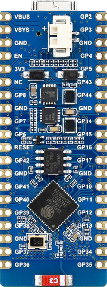
Pin Configuration and Descriptions
| Pin Number | Pin Name | Description |
|---|---|---|
| 1 | 3V3 | 3.3V power supply input |
| 2 | GND | Ground |
| 3 | GPIO0 | General-purpose I/O, boot mode selection |
| 4 | GPIO1 | General-purpose I/O, UART TX |
| 5 | GPIO2 | General-purpose I/O, UART RX |
| 6 | GPIO12 | SPI MOSI |
| 7 | GPIO13 | SPI MISO |
| 8 | GPIO14 | SPI SCK |
| 9 | GPIO15 | SPI CS |
| 10 | SDA | I2C Data Line |
| 11 | SCL | I2C Clock Line |
| 12 | LCD_RST | LCD Reset Pin |
| 13 | LCD_DC | LCD Data/Command Control |
| 14 | LCD_CS | LCD Chip Select |
| 15 | LCD_BL | LCD Backlight Control |
Usage Instructions
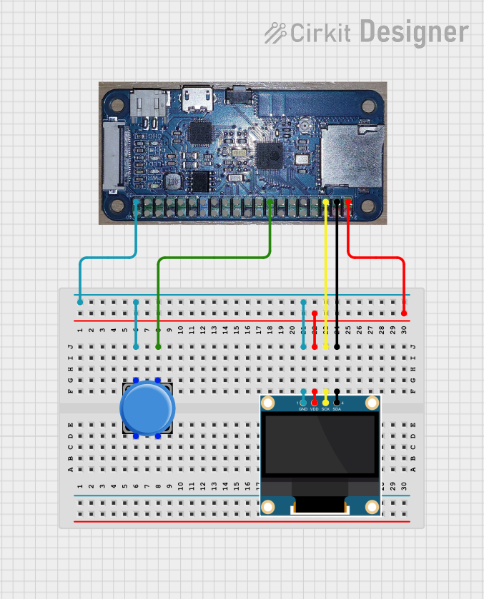
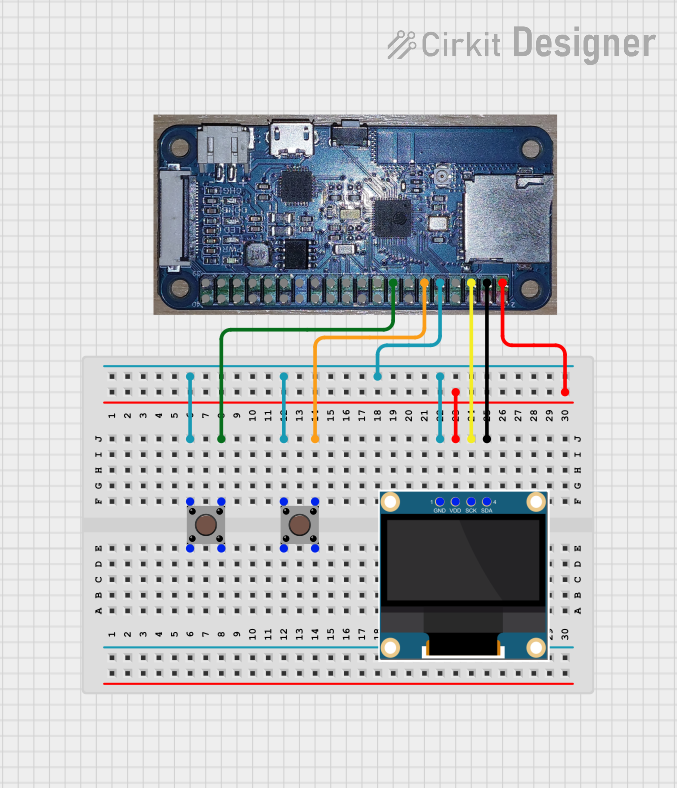
How to Use the ESP32-S2-LCD-0.96 in a Circuit
- Power Supply: Connect the 3V3 pin to a 3.3V power source and GND to ground.
- LCD Connections: Use the LCD_RST, LCD_DC, LCD_CS, and LCD_BL pins to control the display. Ensure proper initialization in your code.
- GPIO Usage: Configure GPIO pins for input/output as needed. Use pull-up or pull-down resistors if required.
- Communication Interfaces: Use I2C, SPI, or UART for connecting peripherals like sensors or actuators.
- Programming: Program the ESP32-S2 using the Arduino IDE, ESP-IDF, or other compatible environments.
Important Considerations and Best Practices
- Voltage Levels: Ensure all connected peripherals operate at 3.3V logic levels to avoid damage.
- Power Consumption: Use the ultra-low power modes for battery-powered applications.
- LCD Initialization: Properly initialize the LCD in your code to avoid display issues.
- Wi-Fi and Bluetooth: Avoid placing the module near metal objects to ensure optimal wireless performance.
Example Code for Arduino IDE
Below is an example of initializing the LCD and displaying text using the Arduino IDE:
#include <TFT_eSPI.h> // Include the TFT library for ESP32-S2

TFT_eSPI tft = TFT_eSPI(); // Create an instance of the TFT library

void setup() {
  tft.init(); // Initialize the LCD
  tft.setRotation(1); // Set display orientation
  tft.fillScreen(TFT_BLACK); // Clear the screen with black color

  tft.setTextColor(TFT_WHITE, TFT_BLACK); // Set text color and background
  tft.setTextSize(2); // Set text size

  tft.setCursor(10, 10); // Set cursor position
  tft.println("Hello, ESP32-S2!"); // Display text on the screen
}

void loop() {
  // Add your main code here
}
Note: Ensure the
TFT_eSPIlibrary is installed and configured for the ESP32-S2-LCD-0.96 module.
Troubleshooting and FAQs
Common Issues and Solutions
LCD Not Displaying Anything
- Cause: Incorrect wiring or missing initialization in the code.
- Solution: Double-check the connections to the LCD pins and ensure the
tft.init()function is called in the setup.
Wi-Fi or Bluetooth Not Working
- Cause: Poor signal strength or incorrect configuration.
- Solution: Ensure the module is in an open area with minimal interference. Verify Wi-Fi credentials and Bluetooth pairing settings.
Module Not Powering On
- Cause: Insufficient power supply or incorrect voltage.
- Solution: Ensure the input voltage is within the 3.0V - 3.6V range and the power source can supply sufficient current.
GPIO Pins Not Responding
- Cause: Incorrect pin configuration or missing pull-up/pull-down resistors.
- Solution: Verify the pinMode settings in your code and add external resistors if necessary.
FAQs
Q: Can I use the ESP32-S2-LCD-0.96 with a 5V power supply?
A: No, the module operates at 3.3V. Using a 5V supply can damage the module.Q: Is the LCD backlight adjustable?
A: Yes, you can control the backlight brightness using the LCD_BL pin with PWM.Q: What is the maximum range for Wi-Fi?
A: The Wi-Fi range is typically up to 50 meters indoors and 200 meters outdoors, depending on the environment.Q: Can I use the ESP32-S2-LCD-0.96 with the Arduino UNO?
A: No, the ESP32-S2 is a standalone microcontroller and does not require an Arduino UNO. However, it can communicate with other microcontrollers via I2C, SPI, or UART.