
How to Use PWM DC Controller (backside): Examples, Pinouts, and Specs
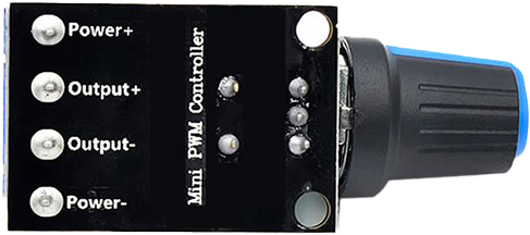
 Design with PWM DC Controller (backside) in Cirkit Designer
Introduction
The PWM DC Controller is an electronic component designed to regulate the voltage and current supplied to a load by varying the width of the pulses in a signal. This method of control, known as Pulse Width Modulation (PWM), allows for efficient power delivery and precise control of devices such as DC motors, LEDs, and heating elements. The "backside" designation refers to the physical layout of the controller, where the connections and components are typically located on the rear side of the module.
Explore Projects Built with PWM DC Controller (backside)
 Open Project in Cirkit Designer
 Open Project in Cirkit Designer
 Open Project in Cirkit Designer
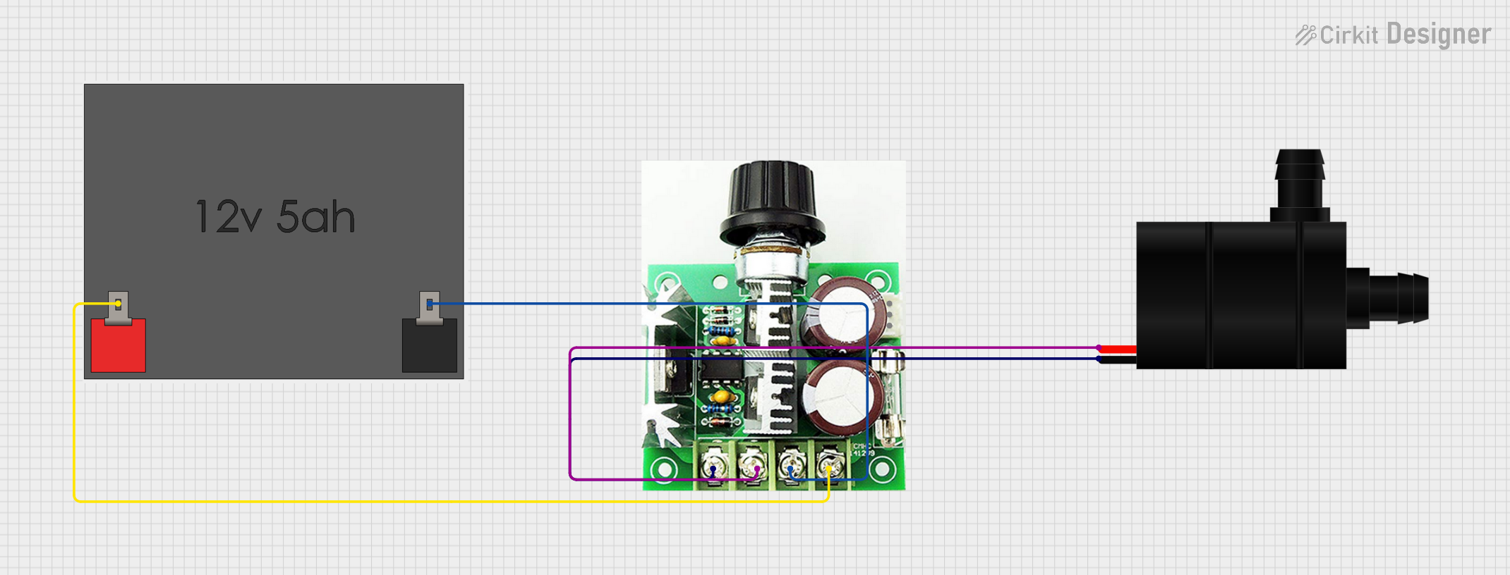 Open Project in Cirkit Designer
Explore Projects Built with PWM DC Controller (backside)
Open Project in Cirkit DesignerOpen Project in Cirkit DesignerOpen Project in Cirkit DesignerOpen Project in Cirkit DesignerCommon Applications and Use Cases
- DC Motor Speed Control: Adjust the speed of DC motors in robotics, fans, and other applications.
- LED Dimming: Control the brightness of LEDs without sacrificing efficiency.
- Power Regulation: Efficiently manage power delivery to resistive or inductive loads.
- Battery-Powered Devices: Extend battery life by optimizing power usage.
Technical Specifications
The PWM DC Controller is designed to handle a wide range of power control applications. Below are the key technical details:
General Specifications
| Parameter | Value |
|---|---|
| Input Voltage Range | 6V to 60V DC |
| Output Voltage Range | 0V to Input Voltage |
| Maximum Output Current | 20A |
| PWM Frequency | 15 kHz |
| Duty Cycle Range | 0% to 100% |
| Efficiency | Up to 98% |
| Operating Temperature | -20°C to 60°C |
Pin Configuration and Descriptions
| Pin Name | Description |
|---|---|
| VIN+ | Positive input voltage terminal (connect to the positive terminal of the power source). |
| VIN- | Negative input voltage terminal (connect to the negative terminal of the power source). |
| VOUT+ | Positive output voltage terminal (connect to the positive terminal of the load). |
| VOUT- | Negative output voltage terminal (connect to the negative terminal of the load). |
| Potentiometer | Adjustable knob to control the duty cycle (and thus the output power). |
Usage Instructions
How to Use the PWM DC Controller in a Circuit
Connect the Power Source:
- Attach the positive terminal of the power source to the
VIN+pin. - Attach the negative terminal of the power source to the
VIN-pin.
- Attach the positive terminal of the power source to the
Connect the Load:
- Connect the positive terminal of the load (e.g., motor or LED) to the
VOUT+pin. - Connect the negative terminal of the load to the
VOUT-pin.
- Connect the positive terminal of the load (e.g., motor or LED) to the
Adjust the Potentiometer:
- Rotate the potentiometer to adjust the duty cycle. Turning it clockwise typically increases the duty cycle, resulting in higher output power.
Power On:
- Turn on the power source. The PWM DC Controller will regulate the output voltage and current based on the duty cycle set by the potentiometer.
Important Considerations and Best Practices
- Load Compatibility: Ensure the load does not exceed the maximum output current (20A) or voltage range.
- Heat Dissipation: For high-power applications, ensure adequate cooling (e.g., heat sinks or fans) to prevent overheating.
- Polarity: Double-check the polarity of all connections to avoid damage to the controller or connected devices.
- PWM Frequency: The fixed frequency of 15 kHz is suitable for most applications, but ensure it meets the requirements of your specific load.
Example: Controlling a DC Motor with Arduino UNO
The PWM DC Controller can be used in conjunction with an Arduino UNO to control a DC motor. Below is an example code snippet:
// Example: Controlling a DC motor using Arduino and PWM DC Controller
// Connect the Arduino PWM pin (e.g., D9) to the PWM input of the controller.

const int pwmPin = 9; // PWM output pin connected to the controller

void setup() {
  pinMode(pwmPin, OUTPUT); // Set the PWM pin as an output
}

void loop() {
  // Gradually increase motor speed
  for (int dutyCycle = 0; dutyCycle <= 255; dutyCycle++) {
    analogWrite(pwmPin, dutyCycle); // Write PWM signal to the controller
    delay(10); // Small delay for smooth acceleration
  }

  // Gradually decrease motor speed
  for (int dutyCycle = 255; dutyCycle >= 0; dutyCycle--) {
    analogWrite(pwmPin, dutyCycle); // Write PWM signal to the controller
    delay(10); // Small delay for smooth deceleration
  }
}
Note: Ensure the Arduino's ground (GND) is connected to the VIN- pin of the PWM DC Controller for proper operation.
Troubleshooting and FAQs
Common Issues and Solutions
No Output Voltage:
- Cause: Incorrect wiring or polarity.
- Solution: Verify all connections and ensure the power source and load are properly connected.
Overheating:
- Cause: Excessive current draw or inadequate cooling.
- Solution: Ensure the load does not exceed the maximum current rating (20A). Add a heat sink or fan if necessary.
Load Not Responding to Potentiometer Adjustments:
- Cause: Faulty potentiometer or incorrect wiring.
- Solution: Check the potentiometer for damage and ensure it is properly connected.
PWM Signal Not Detected (when using with Arduino):
- Cause: Missing ground connection between Arduino and controller.
- Solution: Connect the Arduino GND to the
VIN-pin of the controller.
FAQs
Can I use this controller with an AC load?
- No, this controller is designed for DC loads only.
What happens if I exceed the maximum current rating?
- Exceeding the current rating may damage the controller or cause it to shut down. Use a load within the specified limits.
Can I control multiple loads simultaneously?
- Yes, as long as the total current draw does not exceed 20A.
Is the PWM frequency adjustable?
- No, the PWM frequency is fixed at 15 kHz.
By following this documentation, you can effectively use the PWM DC Controller for a variety of applications while ensuring safe and reliable operation.