
How to Use 0.96" OLED: Examples, Pinouts, and Specs
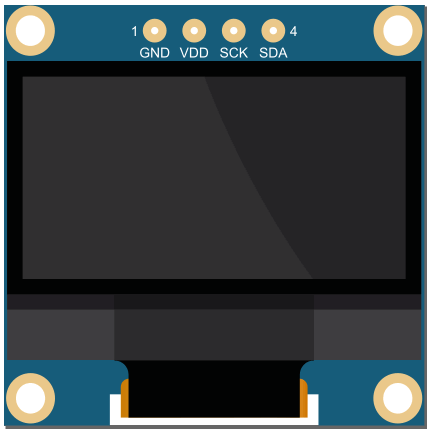
 Design with 0.96" OLED in Cirkit Designer
Introduction
The 0.96" OLED is a small, low-power organic light-emitting diode display that provides high contrast and vibrant colors. It is widely used in embedded systems and microcontroller projects for displaying text, graphics, and animations. This display is particularly popular due to its compact size, low power consumption, and ability to deliver sharp visuals without requiring a backlight.
Explore Projects Built with 0.96" OLED
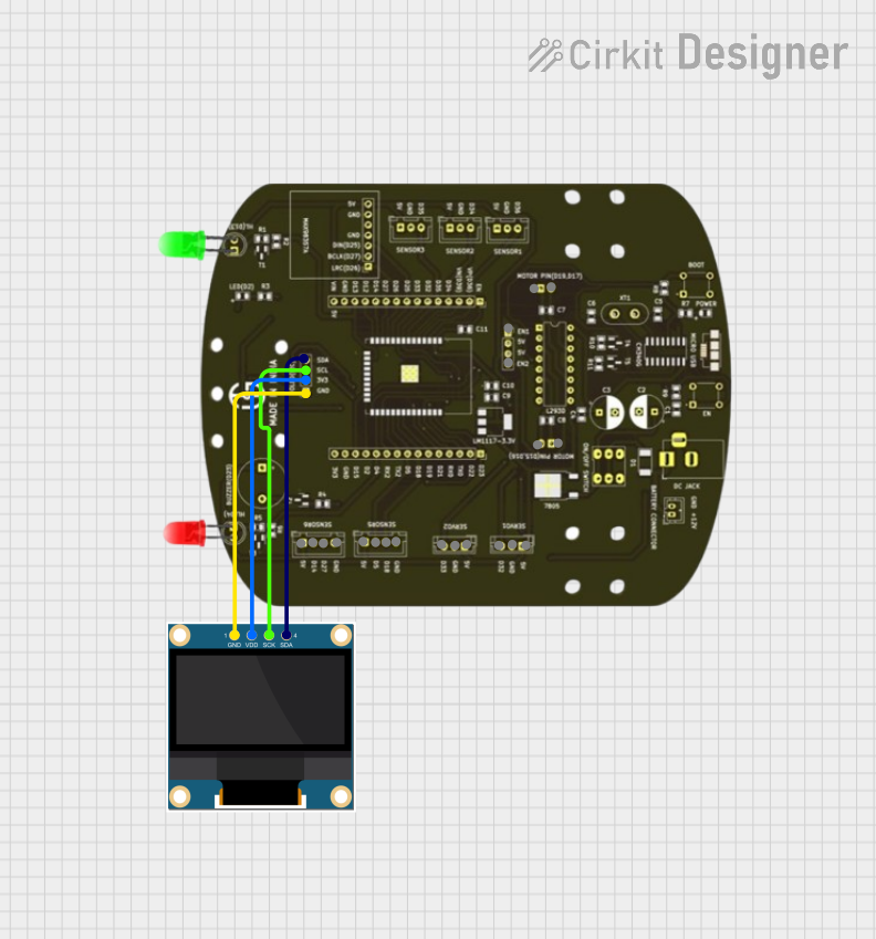 Open Project in Cirkit Designer
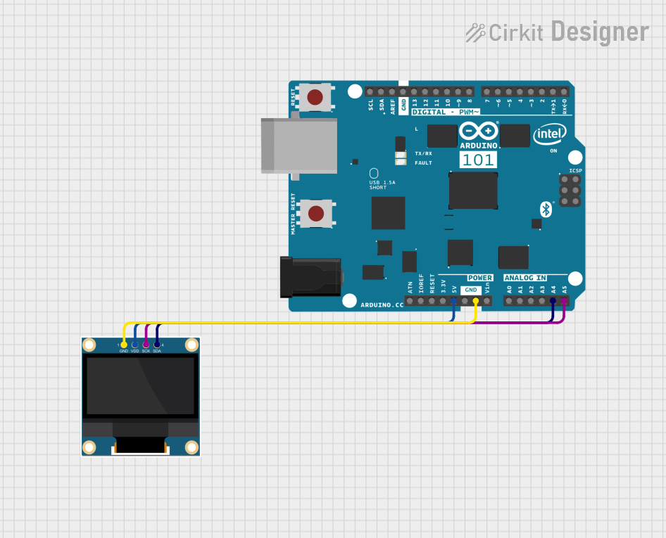 Open Project in Cirkit Designer
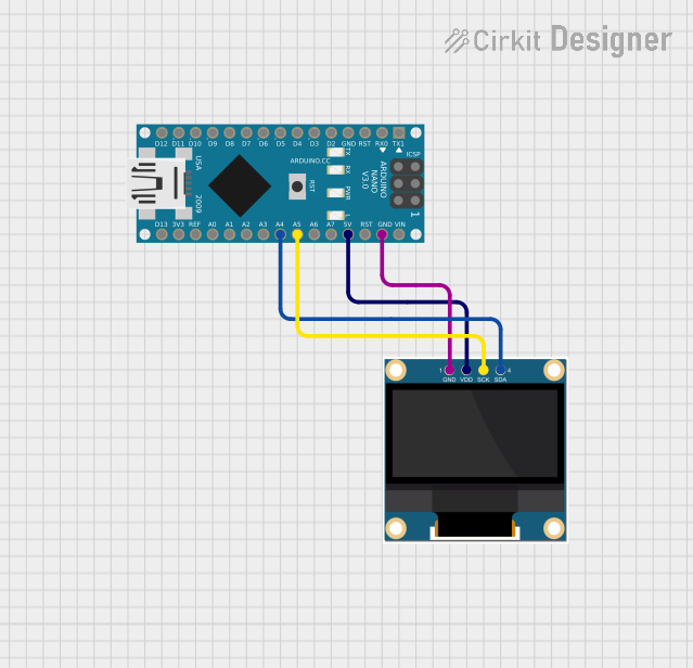 Open Project in Cirkit Designer
 Open Project in Cirkit Designer
Explore Projects Built with 0.96" OLED
Open Project in Cirkit DesignerOpen Project in Cirkit DesignerOpen Project in Cirkit DesignerOpen Project in Cirkit DesignerCommon Applications and Use Cases
- Microcontroller-based projects (e.g., Arduino, Raspberry Pi)
- Wearable devices and portable electronics
- IoT dashboards and data visualization
- Sensor data display
- Custom user interfaces for embedded systems
Technical Specifications
The 0.96" OLED display is typically based on the SSD1306 driver IC, which communicates via I2C or SPI protocols. Below are the key technical details:
Key Technical Details
| Parameter | Specification |
|---|---|
| Display Type | OLED (Organic Light-Emitting Diode) |
| Screen Size | 0.96 inches |
| Resolution | 128 x 64 pixels |
| Driver IC | SSD1306 |
| Interface | I2C (default) or SPI |
| Operating Voltage | 3.3V to 5V |
| Power Consumption | ~20mA (typical) |
| Viewing Angle | >160° |
| Pixel Color | Monochrome (usually white or blue) |
| Operating Temperature | -40°C to +85°C |
Pin Configuration and Descriptions
The 0.96" OLED module typically has 4 or 7 pins, depending on the interface used. Below is the pinout for the I2C configuration (4-pin version):
| Pin Name | Description |
|---|---|
| GND | Ground (0V reference) |
| VCC | Power supply (3.3V or 5V) |
| SCL | Serial Clock Line for I2C communication |
| SDA | Serial Data Line for I2C communication |
For the SPI configuration (7-pin version), the pinout is as follows:
| Pin Name | Description |
|---|---|
| GND | Ground (0V reference) |
| VCC | Power supply (3.3V or 5V) |
| D0 (SCK) | Serial Clock Line for SPI communication |
| D1 (MOSI) | Master Out Slave In (data line for SPI) |
| RES | Reset pin (active low) |
| DC | Data/Command control pin |
| CS | Chip Select (active low) |
Usage Instructions
How to Use the 0.96" OLED in a Circuit
- Power the Display: Connect the
VCCpin to a 3.3V or 5V power source and theGNDpin to ground. - Connect Communication Lines:
- For I2C: Connect the
SCLandSDApins to the corresponding I2C pins on your microcontroller. - For SPI: Connect
D0,D1,RES,DC, andCSto the appropriate SPI pins on your microcontroller.
- For I2C: Connect the
- Install Required Libraries: If using an Arduino, install the
Adafruit_SSD1306andAdafruit_GFXlibraries via the Arduino Library Manager. - Write Code: Use the libraries to initialize the display and send data for rendering text or graphics.
Important Considerations and Best Practices
- Voltage Compatibility: Ensure the display's operating voltage matches your microcontroller's logic level (3.3V or 5V).
- Pull-Up Resistors: For I2C communication, ensure pull-up resistors (typically 4.7kΩ) are present on the
SCLandSDAlines. - Avoid Static Damage: Handle the OLED module carefully to prevent damage from electrostatic discharge (ESD).
- Contrast Settings: Adjust the display contrast in software to optimize visibility and reduce power consumption.
Example Code for Arduino UNO (I2C)
#include <Wire.h>
#include <Adafruit_GFX.h>
#include <Adafruit_SSD1306.h>

// Define OLED display dimensions
#define SCREEN_WIDTH 128
#define SCREEN_HEIGHT 64

// Create an SSD1306 display object (I2C address is usually 0x3C)
Adafruit_SSD1306 display(SCREEN_WIDTH, SCREEN_HEIGHT, &Wire, -1);

void setup() {
  // Initialize serial communication for debugging
  Serial.begin(9600);

  // Initialize the OLED display
  if (!display.begin(SSD1306_I2C_ADDRESS, 0x3C)) {
    Serial.println(F("SSD1306 allocation failed"));
    for (;;); // Halt execution if initialization fails
  }

  // Clear the display buffer
  display.clearDisplay();

  // Display a welcome message
  display.setTextSize(1);      // Set text size (1 = small, 2 = medium, etc.)
  display.setTextColor(SSD1306_WHITE); // Set text color
  display.setCursor(0, 0);     // Set cursor position (x, y)
  display.println(F("Hello, OLED!")); // Print text to the buffer
  display.display();           // Render the buffer to the screen
}

void loop() {
  // Add your code here to update the display dynamically
}
Troubleshooting and FAQs
Common Issues and Solutions
Display Not Turning On:
- Verify the power connections (
VCCandGND). - Ensure the correct operating voltage (3.3V or 5V) is supplied.
- Check for loose or incorrect wiring.
- Verify the power connections (
No Output on the Screen:
- Confirm the I2C address (default is
0x3C) matches the one in your code. - Ensure the required libraries (
Adafruit_SSD1306andAdafruit_GFX) are installed. - Check the
SCLandSDAconnections for proper communication.
- Confirm the I2C address (default is
Flickering or Artifacts:
- Verify that the power supply is stable and sufficient.
- Check for noise or interference on the communication lines.
Partial or Distorted Display:
- Ensure the display dimensions (
128x64) are correctly defined in the code. - Reset the display by toggling the
RESpin (if available).
- Ensure the display dimensions (
FAQs
Q: Can I use the 0.96" OLED with a 3.3V microcontroller?
A: Yes, the display is compatible with both 3.3V and 5V logic levels.
Q: How do I change the I2C address of the display?
A: Some modules allow changing the I2C address by soldering jumpers on the back of the PCB. Refer to the module's datasheet for details.
Q: Can I use this display for animations?
A: Yes, the SSD1306 driver supports fast updates, making it suitable for simple animations.
Q: Is the display sunlight-readable?
A: The OLED provides high contrast but is not optimized for direct sunlight readability.