
How to Use stm32f401re1: Examples, Pinouts, and Specs
 Design with stm32f401re1 in Cirkit Designer
Introduction
The STM32F401RE1 is a high-performance microcontroller manufactured by Bala (Part ID: stm). It is part of the STM32 family and is based on the 32-bit ARM Cortex-M4 core. Operating at a maximum frequency of 84 MHz, this microcontroller is designed for applications requiring efficient processing, low power consumption, and robust peripheral integration.
With 512 KB of Flash memory and 128 KB of SRAM, the STM32F401RE1 is ideal for embedded systems, IoT devices, industrial automation, and consumer electronics. It supports a wide range of peripherals, including ADCs, timers, and communication interfaces like UART, SPI, and I2C, making it versatile for various use cases.
Explore Projects Built with stm32f401re1
 Open Project in Cirkit Designer
 Open Project in Cirkit Designer
 Open Project in Cirkit Designer
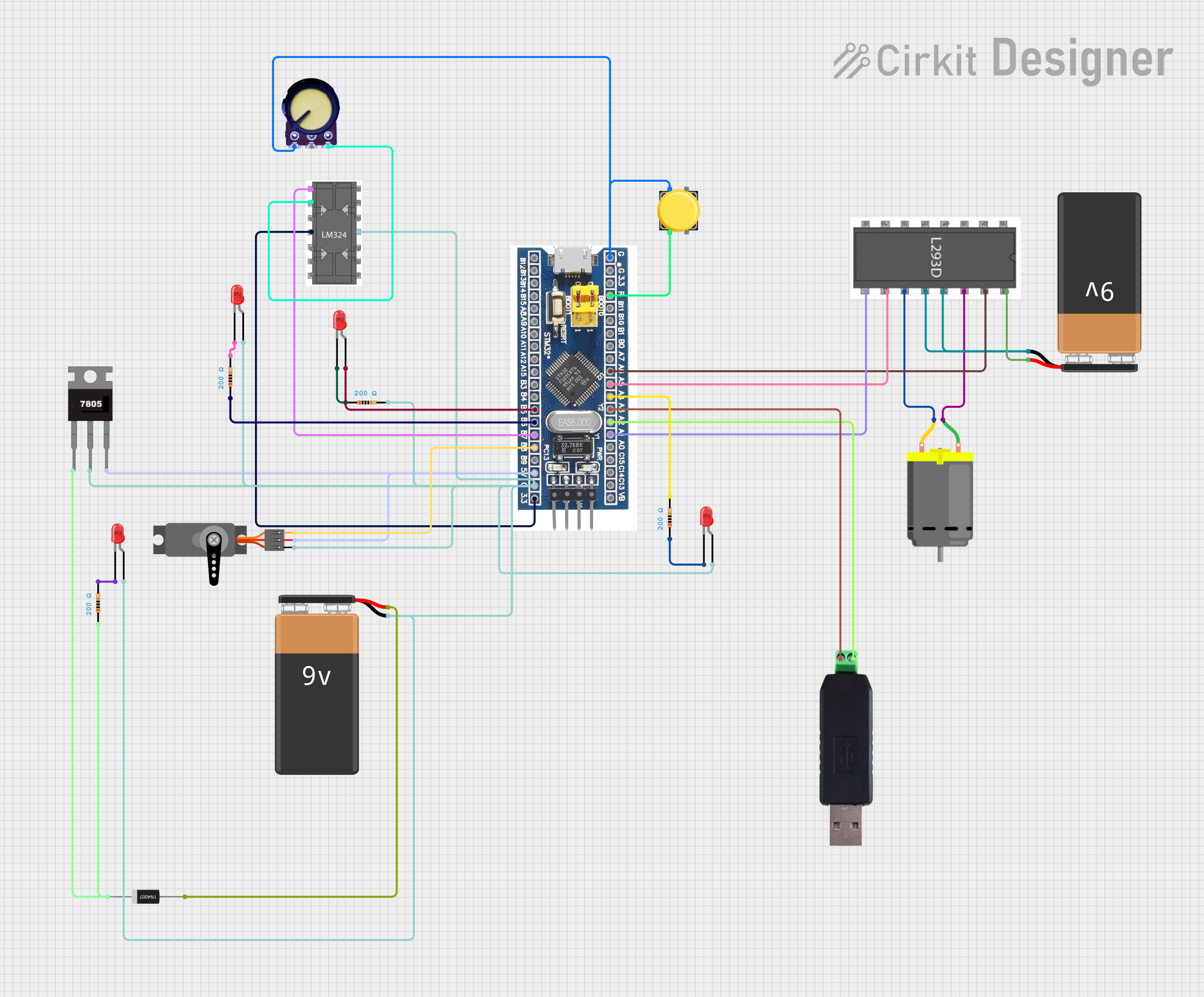 Open Project in Cirkit Designer
Explore Projects Built with stm32f401re1
Open Project in Cirkit DesignerOpen Project in Cirkit DesignerOpen Project in Cirkit DesignerOpen Project in Cirkit DesignerCommon Applications
- IoT devices and smart home systems
- Industrial automation and control systems
- Wearable devices and portable electronics
- Robotics and motor control
- Data acquisition and signal processing
Technical Specifications
Key Technical Details
| Parameter | Value |
|---|---|
| Core | ARM Cortex-M4 (32-bit) |
| Maximum Clock Frequency | 84 MHz |
| Flash Memory | 512 KB |
| SRAM | 128 KB |
| Operating Voltage Range | 1.7V to 3.6V |
| GPIO Pins | 50 |
| Communication Interfaces | UART, SPI, I2C, CAN, USB OTG |
| Timers | 16-bit and 32-bit timers |
| ADC Resolution | 12-bit |
| Package | LQFP64 (64-pin) |
Pin Configuration and Descriptions
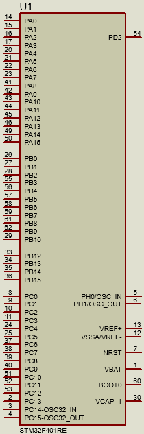
The STM32F401RE1 comes in an LQFP64 package with 64 pins. Below is a summary of key pins and their functions:
| Pin Number | Pin Name | Function |
|---|---|---|
| 1 | VDD | Power supply (1.7V to 3.6V) |
| 2 | VSS | Ground |
| 10 | PA0 | GPIO/ADC Input/EXTI Line 0 |
| 22 | PB6 | I2C1_SCL (I2C Clock Line) |
| 23 | PB7 | I2C1_SDA (I2C Data Line) |
| 37 | PA9 | USART1_TX (UART Transmit) |
| 38 | PA10 | USART1_RX (UART Receive) |
| 50 | PC13 | GPIO/User Button Input |
| 64 | NRST | Reset Pin |
For a complete pinout, refer to the official datasheet.
Usage Instructions
How to Use the STM32F401RE1 in a Circuit
- Power Supply: Connect the VDD pin to a regulated power source (1.7V to 3.6V) and the VSS pin to ground.
- Clock Configuration: Use an external crystal oscillator (e.g., 8 MHz) or the internal RC oscillator for clock generation.
- Programming: Use an ST-Link programmer/debugger to upload firmware via the SWD (Serial Wire Debug) interface.
- Peripherals: Configure GPIOs, ADCs, timers, and communication interfaces (UART, SPI, I2C) as needed for your application.
- Reset: Connect the NRST pin to a push-button or external reset circuit for manual resets.
Important Considerations
- Decoupling Capacitors: Place decoupling capacitors (e.g., 0.1 µF) close to the VDD pins to stabilize the power supply.
- Boot Mode Selection: Use the BOOT0 pin to select between boot modes (e.g., boot from Flash or system memory).
- Debugging: Ensure the SWDIO and SWCLK pins are accessible for debugging and programming.
- GPIO Configuration: Configure unused GPIO pins as analog inputs to reduce power consumption.
Example: Interfacing with an Arduino UNO
The STM32F401RE1 can communicate with an Arduino UNO via UART. Below is an example of Arduino code to send data to the STM32F401RE1:
// Arduino UNO UART Communication Example
// Sends "Hello STM32!" to the STM32F401RE1 via UART

void setup() {
  Serial.begin(9600); // Initialize UART at 9600 baud rate
}

void loop() {
  Serial.println("Hello STM32!"); // Send data to STM32
  delay(1000); // Wait for 1 second
}
On the STM32F401RE1, configure USART1 to receive data from the Arduino UNO.
Troubleshooting and FAQs
Common Issues and Solutions
Microcontroller Not Powering On
- Cause: Incorrect power supply voltage.
- Solution: Ensure the VDD pin is supplied with 1.7V to 3.6V and the VSS pin is connected to ground.
Unable to Program the Microcontroller
- Cause: Incorrect SWD connection or boot mode configuration.
- Solution: Verify the SWDIO and SWCLK connections. Ensure the BOOT0 pin is set to boot from Flash memory.
Peripheral Not Responding
- Cause: Incorrect pin configuration or clock settings.
- Solution: Double-check the peripheral initialization code and ensure the clock source is configured correctly.
High Power Consumption
- Cause: Unused GPIO pins left floating.
- Solution: Configure unused GPIO pins as analog inputs to minimize power consumption.
FAQs
Q: Can the STM32F401RE1 operate at 5V?
A: No, the STM32F401RE1 operates within a voltage range of 1.7V to 3.6V. Use a voltage regulator if your power source exceeds this range.
Q: How do I enable USB communication?
A: The STM32F401RE1 supports USB OTG. Configure the USB peripheral in your firmware and connect the appropriate pins (e.g., PA11 for USB_DM and PA12 for USB_DP).
Q: What development tools are compatible with the STM32F401RE1?
A: Popular tools include STM32CubeIDE, Keil µVision, and IAR Embedded Workbench. Additionally, use an ST-Link programmer for debugging and programming.
This concludes the documentation for the STM32F401RE1 microcontroller. For further details, refer to the official datasheet and reference manual.