How to Use Dual TB9051FTG Motor Driver Shield: Examples, Pinouts, and Specs
Introduction
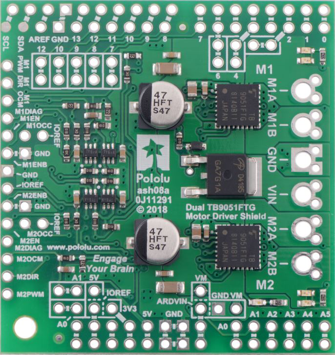
The Dual TB9051FTG Motor Driver Shield (Pololu Part #2520) is a robust and versatile motor driver shield designed for controlling DC motors and stepper motors. It features two Toshiba TB9051FTG motor driver ICs, each capable of driving a single brushed DC motor or one phase of a stepper motor. The shield is compatible with Arduino and other microcontroller platforms, making it an excellent choice for robotics, automation, and other motor control applications.
This shield provides bidirectional control, speed regulation, and built-in protection features such as overcurrent, overvoltage, and thermal shutdown. Its compact design and ease of use make it ideal for both beginners and advanced users.
Explore Projects Built with Dual TB9051FTG Motor Driver Shield


Explore Projects Built with Dual TB9051FTG Motor Driver Shield
Common Applications
- Robotics and automation systems
- Remote-controlled vehicles
- Conveyor belts and industrial machinery
- Stepper motor-based positioning systems
- DIY electronics and hobby projects
Technical Specifications
Key Technical Details
| Parameter | Specification |
|---|---|
| Operating Voltage | 4.5 V to 28 V |
| Continuous Output Current | 2.6 A per channel |
| Peak Output Current | 5 A per channel |
| Logic Voltage | 3.3 V or 5 V (selectable via jumper) |
| PWM Frequency Range | Up to 20 kHz |
| Motor Channels | 2 (independent control for each motor) |
| Control Interface | Arduino-compatible pins (PWM, DIR, EN, etc.) |
| Protection Features | Overcurrent, overvoltage, undervoltage, thermal shutdown, and short-circuit protection |
Pin Configuration and Descriptions
The shield connects to an Arduino or similar microcontroller via standard headers. Below is the pin configuration:
Control Pins
| Pin Name | Description |
|---|---|
| M1PWM | PWM input for Motor 1 speed control |
| M1DIR | Direction control input for Motor 1 |
| M1EN | Enable input for Motor 1 (active high) |
| M2PWM | PWM input for Motor 2 speed control |
| M2DIR | Direction control input for Motor 2 |
| M2EN | Enable input for Motor 2 (active high) |
| FAULT | Fault output (active low) indicating an error condition |
| VOUT | Voltage output for powering external devices (regulated from motor supply) |
Power and Motor Connections
| Pin Name | Description |
|---|---|
| VIN | Motor power supply input (4.5 V to 28 V) |
| GND | Ground connection |
| M1A, M1B | Motor 1 output terminals |
| M2A, M2B | Motor 2 output terminals |
Usage Instructions
How to Use the Shield in a Circuit
- Connect the Shield to an Arduino: Plug the shield into the Arduino's headers. Ensure the pins align correctly.
- Power the Shield: Connect a power supply (4.5 V to 28 V) to the VIN and GND terminals. Ensure the power supply can provide sufficient current for your motors.
- Connect Motors: Attach the DC motors or stepper motor phases to the M1A/M1B and M2A/M2B terminals.
- Set Logic Voltage: Use the onboard jumper to select the logic voltage (3.3 V or 5 V) based on your microcontroller.
- Control the Motors: Use the Arduino's PWM and digital pins to control motor speed and direction.
Important Considerations and Best Practices
- Power Supply: Ensure the power supply voltage matches the motor's requirements and does not exceed 28 V.
- Current Limits: Avoid exceeding the continuous current rating of 2.6 A per channel to prevent overheating.
- Fault Handling: Monitor the FAULT pin to detect and respond to error conditions.
- PWM Frequency: Use a PWM frequency within the recommended range (up to 20 kHz) for optimal performance.
- Heat Dissipation: If operating near the current limits, consider adding a heatsink or fan for better thermal management.
Example Arduino Code
Below is an example Arduino sketch to control two DC motors using the shield:
// Dual TB9051FTG Motor Driver Shield Example
// This code demonstrates basic motor control using PWM and direction pins.

#define M1PWM 9  // PWM pin for Motor 1
#define M1DIR 7  // Direction pin for Motor 1
#define M2PWM 10 // PWM pin for Motor 2
#define M2DIR 8  // Direction pin for Motor 2

void setup() {
  // Set motor control pins as outputs
  pinMode(M1PWM, OUTPUT);
  pinMode(M1DIR, OUTPUT);
  pinMode(M2PWM, OUTPUT);
  pinMode(M2DIR, OUTPUT);
}

void loop() {
  // Motor 1: Forward at 50% speed
  digitalWrite(M1DIR, HIGH); // Set direction forward
  analogWrite(M1PWM, 128);   // Set speed (128/255 = 50%)

  // Motor 2: Reverse at 75% speed
  digitalWrite(M2DIR, LOW);  // Set direction reverse
  analogWrite(M2PWM, 192);   // Set speed (192/255 = 75%)

  delay(2000); // Run motors for 2 seconds

  // Stop both motors
  analogWrite(M1PWM, 0);
  analogWrite(M2PWM, 0);

  delay(1000); // Wait for 1 second before repeating
}
Troubleshooting and FAQs
Common Issues and Solutions
Motors Not Running
- Cause: Incorrect wiring or insufficient power supply.
- Solution: Double-check all connections and ensure the power supply meets the voltage and current requirements.
FAULT Pin is Active (Low)
- Cause: Overcurrent, overvoltage, or thermal shutdown.
- Solution: Reduce the motor load, check the power supply voltage, and ensure proper cooling.
Erratic Motor Behavior
- Cause: Noise or unstable power supply.
- Solution: Add decoupling capacitors near the motor terminals and use a stable power source.
Arduino Not Communicating with Shield
- Cause: Incorrect logic voltage setting or pin configuration.
- Solution: Verify the logic voltage jumper setting and ensure the Arduino pins match the shield's control pins.
FAQs
Can this shield drive stepper motors? Yes, it can drive a bipolar stepper motor by controlling each phase with one motor driver channel.
What happens if the current exceeds 2.6 A? The shield's built-in overcurrent protection will activate, shutting down the affected channel to prevent damage.
Is it compatible with 3.3 V microcontrollers? Yes, the shield supports 3.3 V logic levels. Set the logic voltage jumper accordingly.
Can I stack multiple shields? No, this shield is not designed for stacking due to its pin configuration and power requirements.
This documentation provides a comprehensive guide to using the Pololu Dual TB9051FTG Motor Driver Shield. For further assistance, refer to the manufacturer's datasheet or contact Pololu support.