Cirkit Designer
Your all-in-one circuit design IDE
Home /
Component Documentation
How to Use 600 PPR Optical Rotary Encoder: Examples, Pinouts, and Specs
Introduction
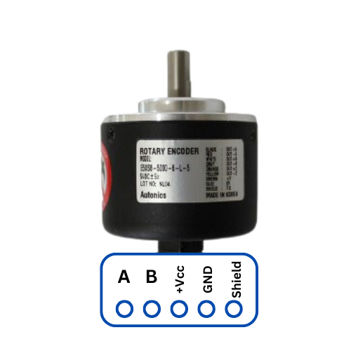
The 600 PPR Optical Rotary Encoder is a precision device designed to convert the angular position or motion of a shaft or axle into an analog or digital signal. With a resolution of 600 pulses per revolution (PPR), this encoder is ideal for applications requiring high accuracy and reliability.
Explore Projects Built with 600 PPR Optical Rotary Encoder
Arduino Mega and Nano-Based Dual Rotary Encoder Controller with AC-DC Power Supply
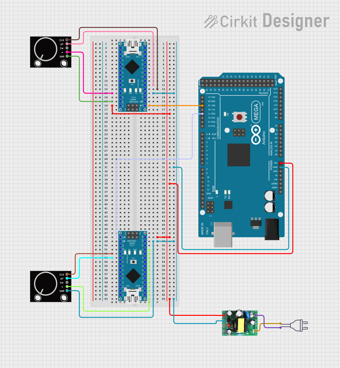
This circuit features an Arduino Mega 2560 and two Arduino Nano microcontrollers interfacing with two rotary encoders for input. The system is powered by an AC-DC PSU board converting 220V AC to 5V DC, and the microcontrollers communicate with each other via serial connections. The setup is designed for reading rotary encoder inputs and potentially processing or transmitting the data.
Arduino Leonardo-Based Gaming Steering Wheel with Pedals and Gear Shifter
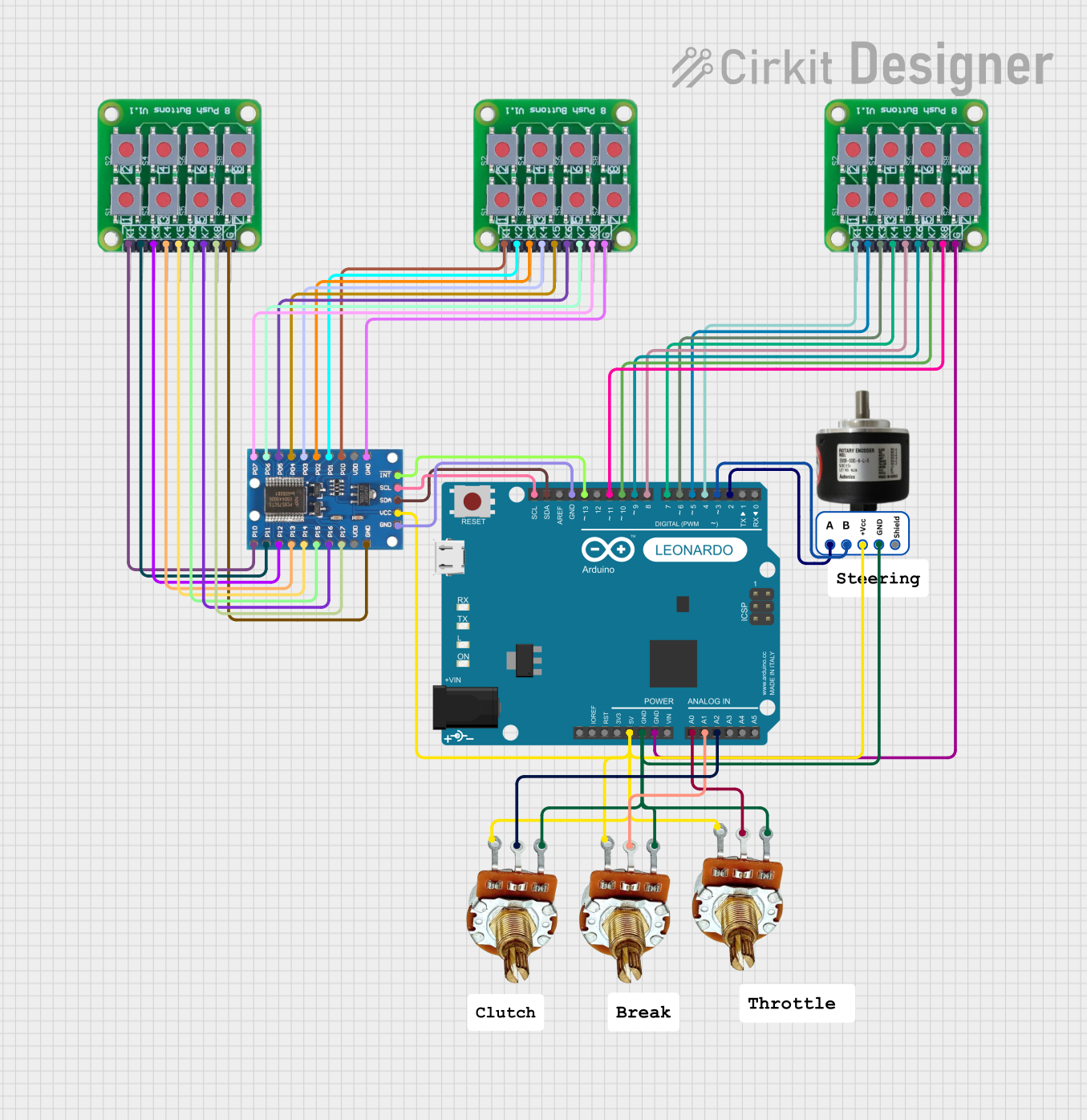
This circuit is a gaming steering wheel system with 3 pedals and a gear shifter, interfaced with an Arduino Leonardo. It includes a 600 PPR optical rotary encoder for steering, three potentiometers for pedal input, and multiple push buttons connected via an IO expander for gear shifting and additional controls. The Arduino processes inputs from these components and communicates the data for further processing or display.
RP2040 Zero Rotary Encoder Interface with Serial Monitoring
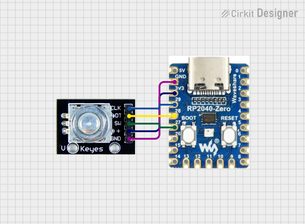
This circuit features an RP2040 Zero microcontroller interfaced with a rotary encoder. The encoder's clock, data, and switch pins are connected to the microcontroller's GPIO pins 29, 28, and 27, respectively, allowing the microcontroller to read the encoder's state and print it to the serial monitor.
Rotary Encoder Interface with STG Adapter for Signal Processing

The circuit consists of two rotary encoders (Kalamoyi P3022-V1-CW360) connected to two STG adapters. Each encoder's VCC, OUT, and GND pins are connected to the corresponding STG adapter, facilitating signal transmission and power supply management.
Explore Projects Built with 600 PPR Optical Rotary Encoder
Arduino Mega and Nano-Based Dual Rotary Encoder Controller with AC-DC Power Supply
This circuit features an Arduino Mega 2560 and two Arduino Nano microcontrollers interfacing with two rotary encoders for input. The system is powered by an AC-DC PSU board converting 220V AC to 5V DC, and the microcontrollers communicate with each other via serial connections. The setup is designed for reading rotary encoder inputs and potentially processing or transmitting the data.
Arduino Leonardo-Based Gaming Steering Wheel with Pedals and Gear Shifter
This circuit is a gaming steering wheel system with 3 pedals and a gear shifter, interfaced with an Arduino Leonardo. It includes a 600 PPR optical rotary encoder for steering, three potentiometers for pedal input, and multiple push buttons connected via an IO expander for gear shifting and additional controls. The Arduino processes inputs from these components and communicates the data for further processing or display.
RP2040 Zero Rotary Encoder Interface with Serial Monitoring
This circuit features an RP2040 Zero microcontroller interfaced with a rotary encoder. The encoder's clock, data, and switch pins are connected to the microcontroller's GPIO pins 29, 28, and 27, respectively, allowing the microcontroller to read the encoder's state and print it to the serial monitor.
Rotary Encoder Interface with STG Adapter for Signal Processing
The circuit consists of two rotary encoders (Kalamoyi P3022-V1-CW360) connected to two STG adapters. Each encoder's VCC, OUT, and GND pins are connected to the corresponding STG adapter, facilitating signal transmission and power supply management.
Common Applications and Use Cases
- Robotics: For precise control of motor positions.
- Industrial Automation: Used in CNC machines, conveyor systems, and other automated machinery.
- Consumer Electronics: In devices like printers and scanners for accurate position tracking.
- Automotive: For monitoring the position of various components such as steering wheels and pedals.
Technical Specifications
Key Technical Details
| Parameter | Value |
|---|---|
| Resolution | 600 PPR |
| Supply Voltage | 5V DC |
| Output Type | Quadrature (A and B channels) |
| Operating Temperature | -20°C to 85°C |
| Shaft Diameter | 6 mm |
| Maximum Speed | 5000 RPM |
| Output Current | 20 mA max |
Pin Configuration and Descriptions
| Pin Number | Pin Name | Description |
|---|---|---|
| 1 | VCC | Power supply (5V DC) |
| 2 | GND | Ground |
| 3 | A | Channel A output |
| 4 | B | Channel B output |
| 5 | Z | Index pulse (optional, if available) |
Usage Instructions
How to Use the Component in a Circuit
- Power Supply: Connect the VCC pin to a 5V DC power supply and the GND pin to the ground.
- Signal Connections: Connect the A and B output pins to the corresponding input pins on your microcontroller or interface circuit.
- Optional Index Pulse: If your application requires an index pulse, connect the Z pin to the appropriate input.
Important Considerations and Best Practices
- Debouncing: Use software or hardware debouncing to filter out noise and ensure accurate readings.
- Pull-up Resistors: If the encoder outputs are open-collector, use pull-up resistors on the A and B channels.
- Mounting: Ensure the encoder is securely mounted to avoid mechanical vibrations that could affect accuracy.
- Alignment: Properly align the encoder shaft with the motor or axle to prevent misalignment and wear.
Example Code for Arduino UNO
// Example code to read a 600 PPR Optical Rotary Encoder with Arduino UNO

const int pinA = 2; // Encoder output A connected to digital pin 2
const int pinB = 3; // Encoder output B connected to digital pin 3

volatile int encoderPos = 0; // Variable to store the encoder position
int lastEncoded = 0; // Variable to store the last encoded value

void setup() {
  pinMode(pinA, INPUT);
  pinMode(pinB, INPUT);
  attachInterrupt(digitalPinToInterrupt(pinA), updateEncoder, CHANGE);
  attachInterrupt(digitalPinToInterrupt(pinB), updateEncoder, CHANGE);
  Serial.begin(9600);
}

void loop() {
  Serial.print("Encoder Position: ");
  Serial.println(encoderPos);
  delay(100);
}

void updateEncoder() {
  int MSB = digitalRead(pinA); // Most significant bit
  int LSB = digitalRead(pinB); // Least significant bit

  int encoded = (MSB << 1) | LSB; // Combine the two bits
  int sum = (lastEncoded << 2) | encoded; // Combine with previous state

  if (sum == 0b1101 || sum == 0b0100 || sum == 0b0010 || sum == 0b1011) {
    encoderPos++;
  }
  if (sum == 0b1110 || sum == 0b0111 || sum == 0b0001 || sum == 0b1000) {
    encoderPos--;
  }

  lastEncoded = encoded; // Store the current state
}
Troubleshooting and FAQs
Common Issues Users Might Face
No Output Signal:
- Solution: Check the power supply connections and ensure the encoder is receiving 5V DC.
Inaccurate Readings:
- Solution: Implement debouncing in software or hardware to filter out noise.
Mechanical Misalignment:
- Solution: Ensure the encoder shaft is properly aligned with the motor or axle.
Solutions and Tips for Troubleshooting
- Check Connections: Ensure all connections are secure and correctly wired.
- Use Pull-up Resistors: If the encoder outputs are open-collector, use appropriate pull-up resistors.
- Monitor Power Supply: Ensure the power supply is stable and within the specified voltage range.
By following this documentation, users can effectively integrate and utilize the 600 PPR Optical Rotary Encoder in their projects, ensuring accurate and reliable performance.