How to Use DSM501A: Examples, Pinouts, and Specs
Introduction
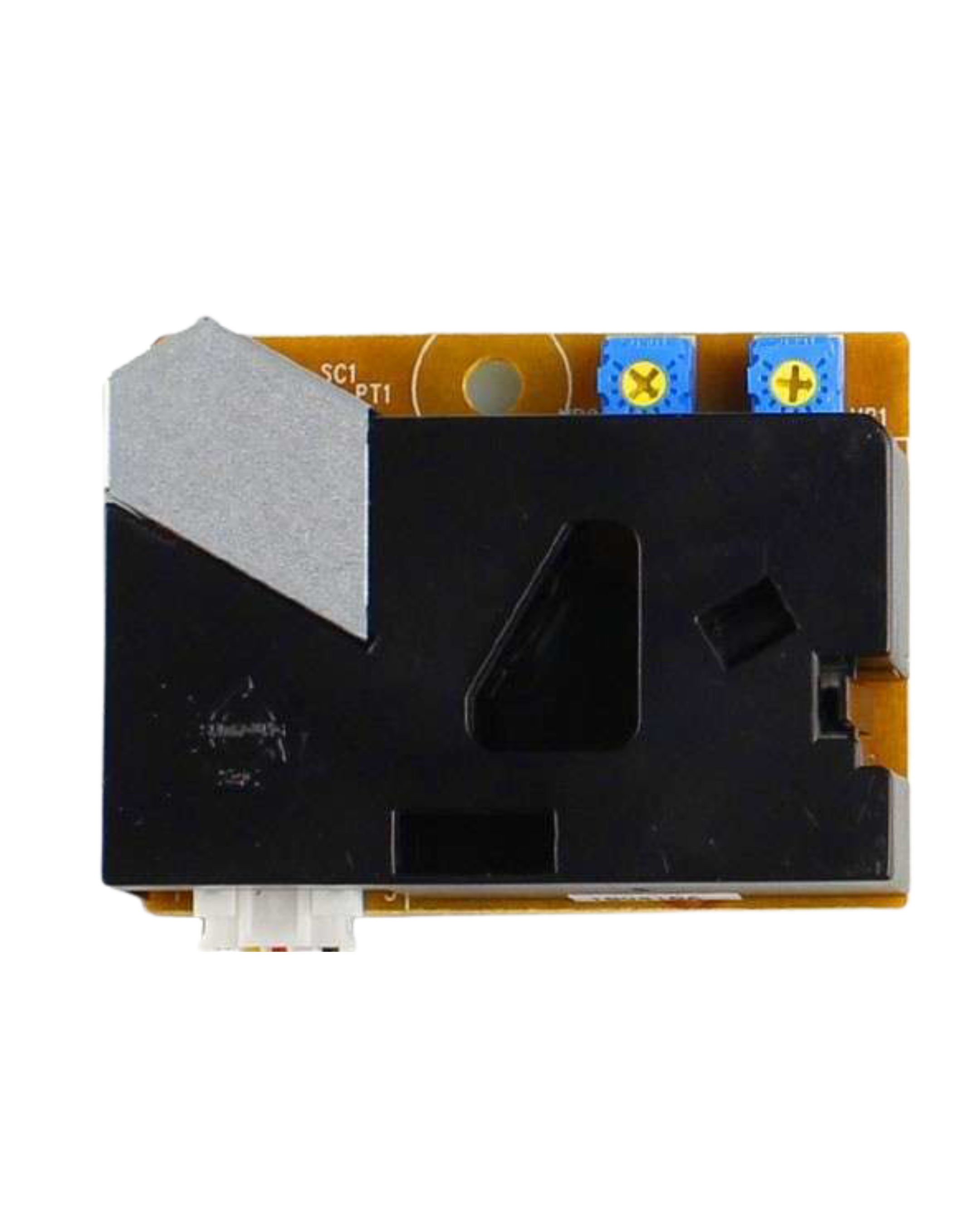
The DSM501A is a digital dust sensor designed to measure particulate matter (PM) in the air. It operates using a laser scattering method to detect and quantify dust particles, providing real-time data on air quality. This sensor is widely used in applications such as environmental monitoring, air purifiers, HVAC systems, and indoor air quality assessment. Its compact design and ease of integration make it a popular choice for both hobbyists and professionals.
Explore Projects Built with DSM501A


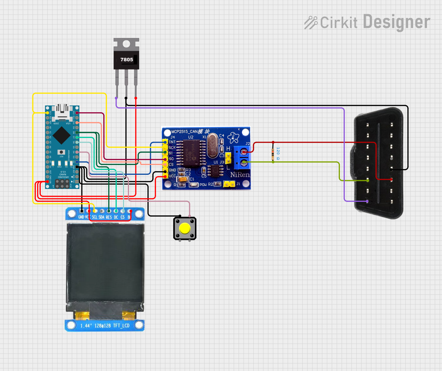
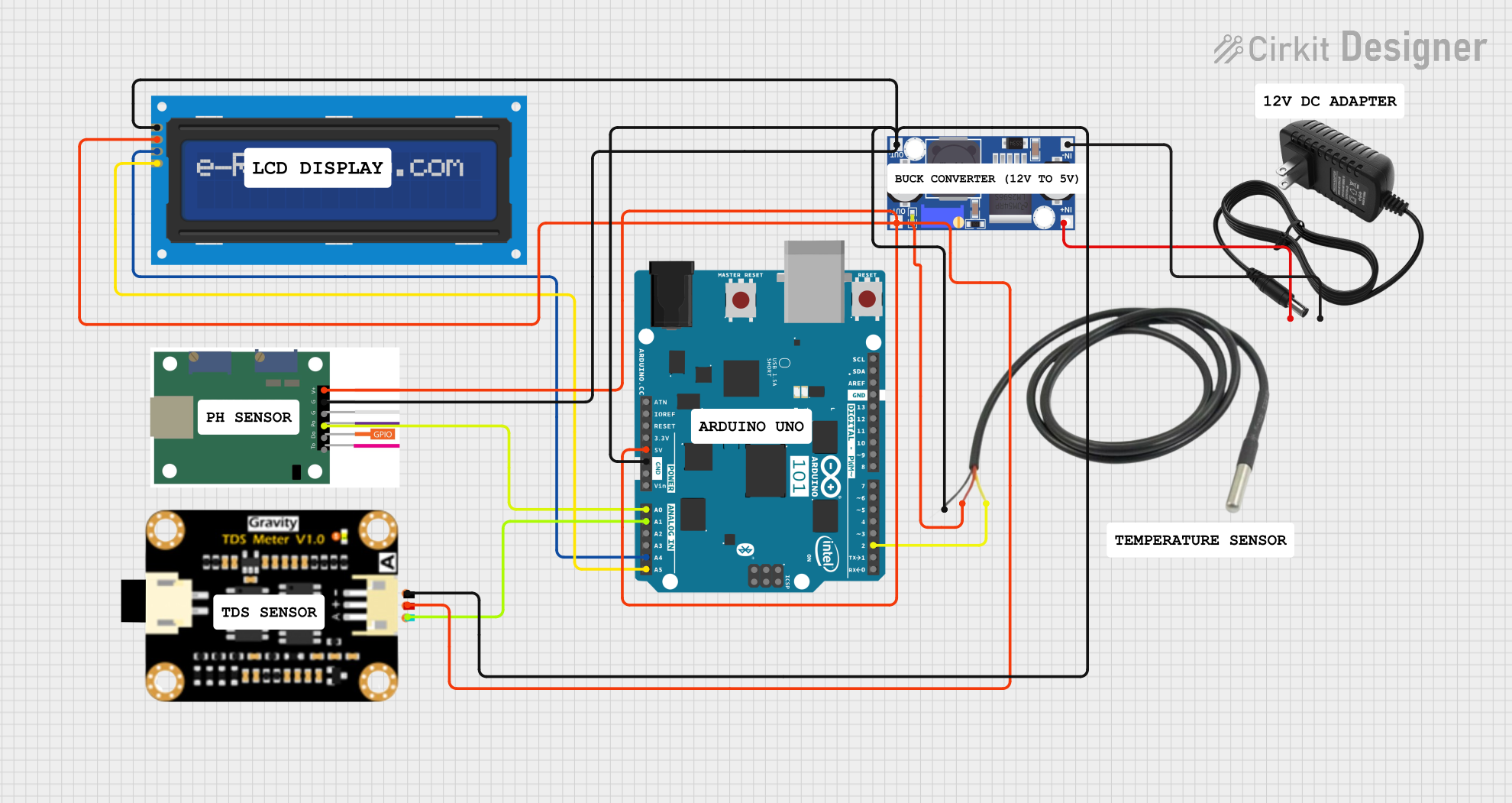
Explore Projects Built with DSM501A
Technical Specifications
The DSM501A is a reliable and efficient sensor with the following key specifications:
| Parameter | Value |
|---|---|
| Operating Voltage | 5V DC |
| Operating Current | ≤ 90 mA |
| Particle Size Detection | ≥ 1 µm |
| Output Signal | Digital PWM |
| Response Time | ≤ 1 second |
| Operating Temperature | -10°C to 65°C |
| Operating Humidity | 95% RH or less (non-condensing) |
| Dimensions | 59 mm x 45 mm x 22 mm |
Pin Configuration and Descriptions
The DSM501A has a 5-pin interface for easy integration into circuits. Below is the pinout description:
| Pin | Name | Description |
|---|---|---|
| 1 | VCC | Power supply input (5V DC) |
| 2 | GND | Ground connection |
| 3 | ILED | Infrared LED control (not commonly used) |
| 4 | OUT1 | Digital PWM output for PM concentration (≥ 1 µm) |
| 5 | OUT2 | Digital PWM output for PM concentration (≥ 2.5 µm) |
Usage Instructions
How to Use the DSM501A in a Circuit
- Power Supply: Connect the VCC pin to a 5V DC power source and the GND pin to ground.
- Signal Output: Use the OUT1 and OUT2 pins to read the digital PWM signals corresponding to particulate matter concentrations. OUT1 detects particles ≥ 1 µm, while OUT2 detects particles ≥ 2.5 µm.
- Signal Processing: The PWM signal can be processed using a microcontroller (e.g., Arduino) to calculate the dust concentration in µg/m³.
Important Considerations and Best Practices
- Placement: Ensure the sensor is placed in an area with good airflow for accurate readings. Avoid placing it near walls or in stagnant air zones.
- Orientation: Install the sensor in the correct orientation as indicated in the datasheet to ensure proper airflow through the sensing chamber.
- Warm-Up Time: Allow the sensor to warm up for at least 1 minute after powering it on for stable readings.
- Filtering Noise: Use capacitors or software-based filtering to reduce noise in the PWM signal.
- Maintenance: Periodically clean the sensor to remove dust buildup, which can affect accuracy.
Example Code for Arduino UNO
Below is an example of how to interface the DSM501A with an Arduino UNO to read and process the PWM signals:
// DSM501A Dust Sensor Example Code for Arduino UNO
// This code reads the PWM signals from OUT1 and OUT2 pins of the DSM501A
// and calculates the dust concentration in µg/m³.

const int OUT1_PIN = 2; // Connect OUT1 (≥ 1 µm particles) to digital pin 2
const int OUT2_PIN = 3; // Connect OUT2 (≥ 2.5 µm particles) to digital pin 3

unsigned long duration1, duration2; // Variables to store pulse durations
float concentration1, concentration2; // Dust concentrations in µg/m³

void setup() {
  pinMode(OUT1_PIN, INPUT);
  pinMode(OUT2_PIN, INPUT);
  Serial.begin(9600); // Initialize serial communication
}

void loop() {
  // Measure the LOW pulse duration for OUT1
  duration1 = pulseIn(OUT1_PIN, LOW);
  // Measure the LOW pulse duration for OUT2
  duration2 = pulseIn(OUT2_PIN, LOW);

  // Calculate the ratio of LOW pulse duration to total period
  float ratio1 = duration1 / 10000.0; // Adjust scaling factor as needed
  float ratio2 = duration2 / 10000.0;

  // Convert the ratio to dust concentration (example formula)
  concentration1 = ratio1 * 1000; // µg/m³ for particles ≥ 1 µm
  concentration2 = ratio2 * 1000; // µg/m³ for particles ≥ 2.5 µm

  // Print the results to the Serial Monitor
  Serial.print("PM ≥ 1 µm: ");
  Serial.print(concentration1);
  Serial.print(" µg/m³, PM ≥ 2.5 µm: ");
  Serial.print(concentration2);
  Serial.println(" µg/m³");

  delay(1000); // Wait 1 second before the next reading
}
Troubleshooting and FAQs
Common Issues and Solutions
No Output Signal:
- Cause: Incorrect wiring or insufficient power supply.
- Solution: Double-check the connections and ensure the sensor is powered with 5V DC.
Inconsistent Readings:
- Cause: Dust buildup inside the sensor or unstable airflow.
- Solution: Clean the sensor and ensure proper placement in an area with consistent airflow.
High Noise in PWM Signal:
- Cause: Electrical noise or interference.
- Solution: Add a capacitor (e.g., 10 µF) between VCC and GND to stabilize the power supply.
Sensor Not Responding After Power-Up:
- Cause: Insufficient warm-up time.
- Solution: Allow the sensor to warm up for at least 1 minute before taking readings.
FAQs
Q1: Can the DSM501A detect particles smaller than 1 µm?
A1: No, the DSM501A is designed to detect particles ≥ 1 µm and ≥ 2.5 µm using its OUT1 and OUT2 pins, respectively.
Q2: How do I clean the sensor?
A2: Use a soft brush or compressed air to gently remove dust from the sensor's inlet and internal components. Avoid using liquids.
Q3: Can I use the DSM501A with a 3.3V microcontroller?
A3: The DSM501A requires a 5V power supply. If your microcontroller operates at 3.3V, use a level shifter for the signal lines.
Q4: What is the lifespan of the DSM501A?
A4: The sensor has a typical lifespan of 5 years under normal operating conditions. Regular maintenance can extend its life.