
How to Use GogoBoard 4.0: Examples, Pinouts, and Specs
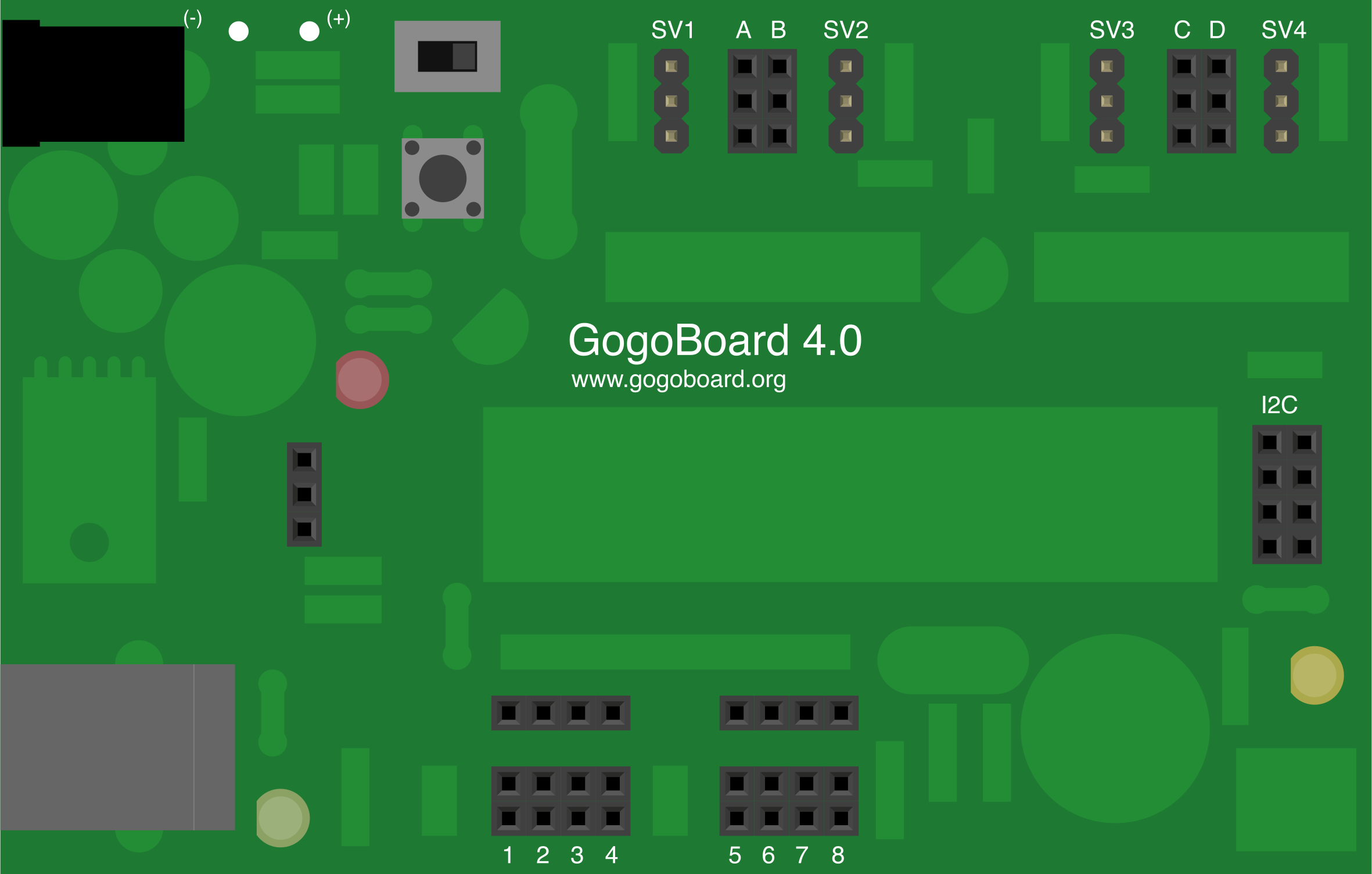
 Design with GogoBoard 4.0 in Cirkit Designer
Introduction
The GogoBoard 4.0, developed by GoGo Board, is a versatile and user-friendly development board designed for rapid prototyping and educational purposes. It features a wide range of input/output options, making it ideal for interfacing with various sensors, actuators, and modules. Its simplicity and flexibility make it a popular choice for educators, hobbyists, and developers working on interactive projects.
Explore Projects Built with GogoBoard 4.0
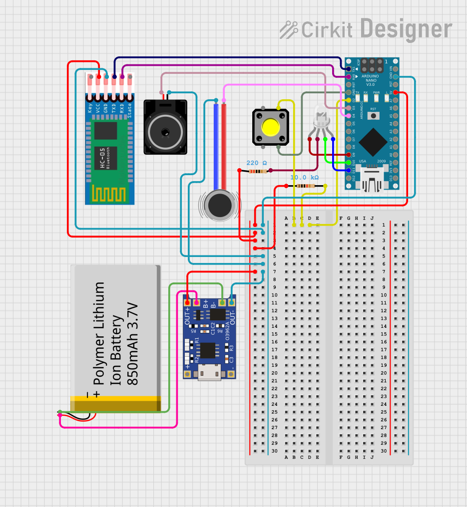 Open Project in Cirkit Designer
 Open Project in Cirkit Designer
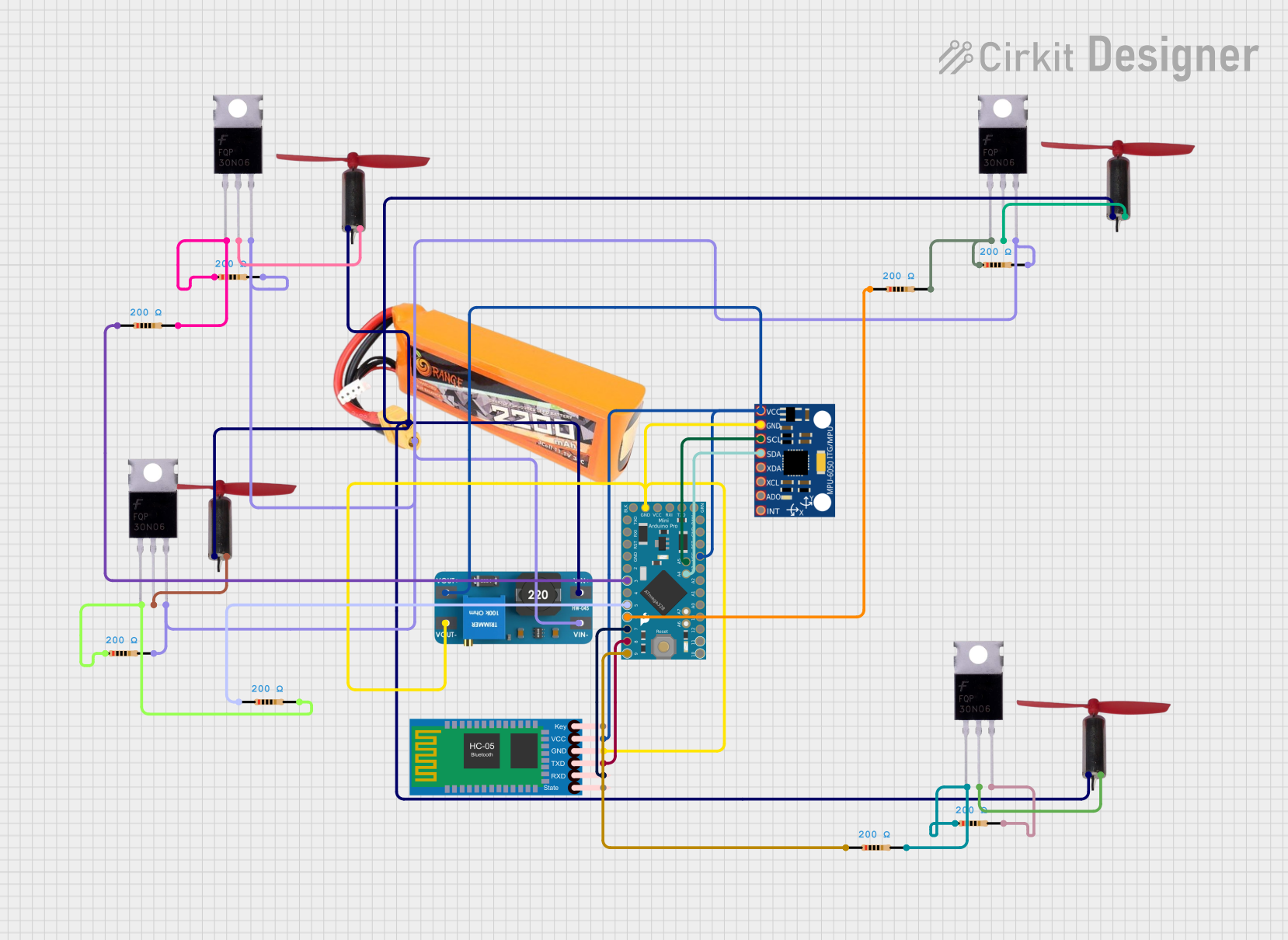 Open Project in Cirkit Designer
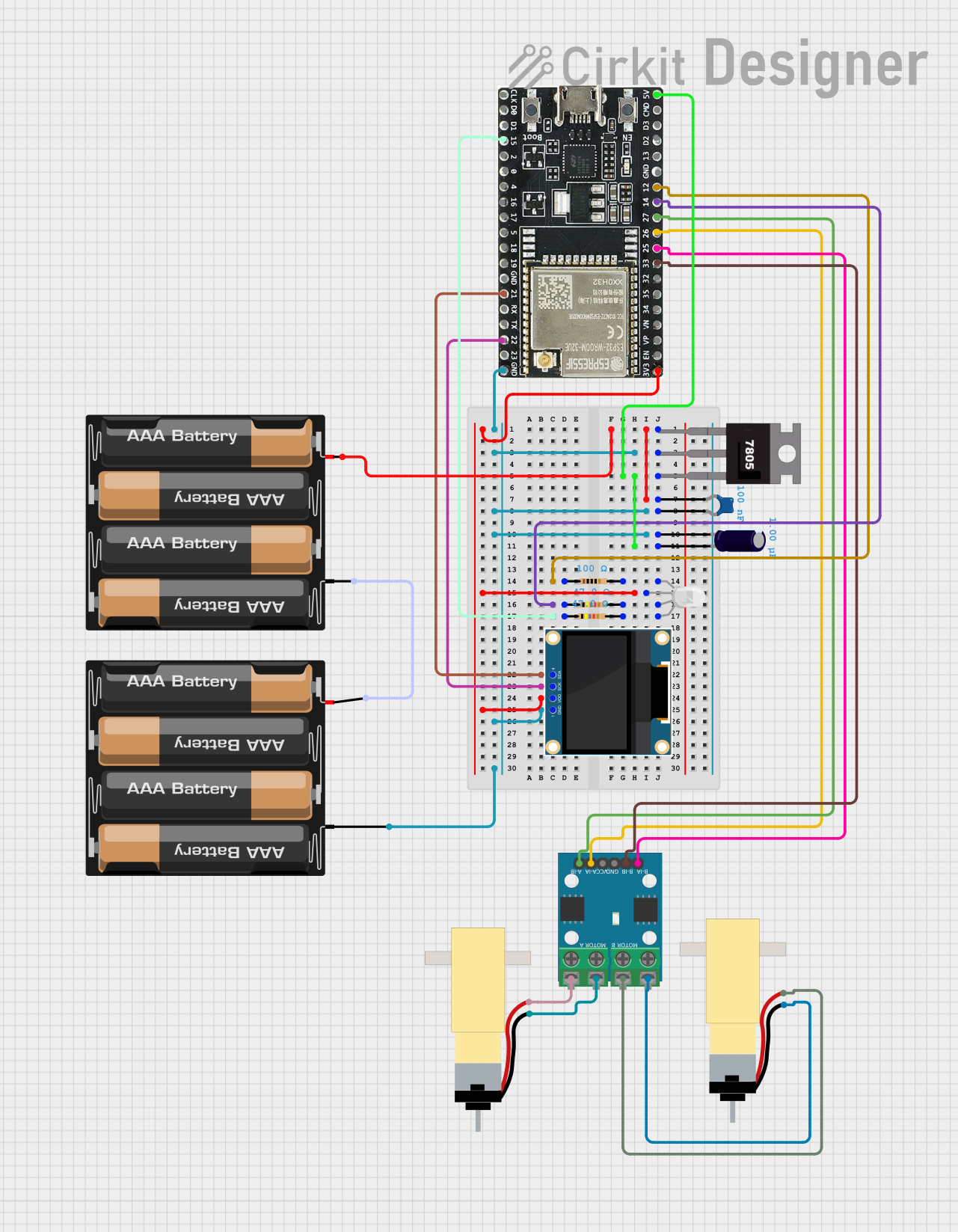 Open Project in Cirkit Designer
Explore Projects Built with GogoBoard 4.0
Open Project in Cirkit DesignerOpen Project in Cirkit DesignerOpen Project in Cirkit DesignerOpen Project in Cirkit DesignerCommon Applications and Use Cases
- Educational robotics and STEM learning
- Rapid prototyping of IoT devices
- Interactive art installations
- Sensor-based data collection and analysis
- Control systems for small-scale automation
Technical Specifications
The GogoBoard 4.0 is equipped with robust hardware features to support a variety of applications. Below are its key technical details:
Key Technical Details
- Microcontroller: 32-bit ARM Cortex-M4
- Operating Voltage: 3.3V
- Input Voltage (recommended): 5V via USB or external power supply
- Digital I/O Pins: 8 (configurable as input or output)
- Analog Input Pins: 4 (10-bit resolution)
- PWM Output Pins: 4
- Communication Interfaces: I2C, UART, SPI
- Power Supply Options: USB or external battery pack
- Programming Interface: USB (compatible with Arduino IDE and custom firmware)
- Dimensions: 85mm x 55mm
- Weight: 40g
Pin Configuration and Descriptions
The GogoBoard 4.0 features a simple and intuitive pin layout. Below is a detailed description of its pin configuration:
| Pin | Type | Description |
|---|---|---|
| D0-D7 | Digital I/O | Configurable as digital input or output pins. |
| A0-A3 | Analog Input | 10-bit resolution analog input pins for sensors and other analog devices. |
| PWM1-4 | PWM Output | Pulse-width modulation pins for controlling motors, LEDs, or other devices. |
| SDA | I2C Data | Data line for I2C communication. |
| SCL | I2C Clock | Clock line for I2C communication. |
| TX | UART Transmit | Transmit pin for UART communication. |
| RX | UART Receive | Receive pin for UART communication. |
| 5V | Power Output | 5V power output for external modules or sensors. |
| GND | Ground | Common ground connection for the circuit. |
Usage Instructions
The GogoBoard 4.0 is designed to be easy to use, even for beginners. Follow the steps below to get started:
How to Use the GogoBoard 4.0 in a Circuit
- Power the Board: Connect the GogoBoard 4.0 to your computer via USB or use an external 5V power supply.
- Connect Sensors and Actuators: Use the digital I/O, analog input, or PWM pins to connect sensors, motors, LEDs, or other devices.
- Program the Board: Write your code using the Arduino IDE or custom firmware. Upload the code to the board via USB.
- Test Your Circuit: Verify that your circuit behaves as expected. Adjust connections or code as needed.
Important Considerations and Best Practices
- Voltage Levels: Ensure that all connected devices operate at 3.3V or use level shifters for compatibility.
- Pin Current Limits: Do not exceed the maximum current rating of 20mA per pin to avoid damage.
- Power Supply: Use a stable power source to prevent unexpected resets or malfunctions.
- Firmware Updates: Regularly check for firmware updates from GoGo Board to ensure optimal performance.
Example Code for Arduino IDE
Below is an example of how to use the GogoBoard 4.0 to read an analog sensor and control an LED:
// Example: Reading an analog sensor and controlling an LED
const int sensorPin = A0; // Analog pin connected to the sensor
const int ledPin = D3;    // Digital pin connected to the LED

void setup() {
  pinMode(ledPin, OUTPUT); // Set the LED pin as an output
  Serial.begin(9600);      // Initialize serial communication
}

void loop() {
  int sensorValue = analogRead(sensorPin); // Read the sensor value
  Serial.println(sensorValue);            // Print the value to the Serial Monitor

  // Map the sensor value to a PWM range (0-255) and write to the LED
  int ledBrightness = map(sensorValue, 0, 1023, 0, 255);
  analogWrite(ledPin, ledBrightness);

  delay(100); // Small delay for stability
}
Troubleshooting and FAQs
Common Issues and Solutions
Board Not Detected by Computer
- Ensure the USB cable is properly connected.
- Try a different USB cable or port.
- Install the necessary drivers for the GogoBoard 4.0.
Code Upload Fails
- Verify that the correct board and port are selected in the Arduino IDE.
- Check for syntax errors in your code.
- Reset the board and try uploading again.
Sensors or Actuators Not Responding
- Double-check the wiring and pin connections.
- Ensure the devices are compatible with the board's voltage and current ratings.
- Test the devices individually to confirm they are functional.
FAQs
Q: Can I use the GogoBoard 4.0 with a battery pack?
A: Yes, the board supports external power supplies, including battery packs, as long as the voltage is within the recommended range (5V).
Q: Is the GogoBoard 4.0 compatible with Arduino libraries?
A: Yes, the board is compatible with most Arduino libraries, making it easy to integrate with existing projects.
Q: How do I update the firmware?
A: Visit the official GoGo Board website for firmware updates and follow the provided instructions.
Q: Can I connect multiple I2C devices?
A: Yes, the GogoBoard 4.0 supports multiple I2C devices as long as each device has a unique address.
By following this documentation, you can effectively utilize the GogoBoard 4.0 for your projects and troubleshoot common issues with ease.