How to Use 12V Solenoid Lock: Examples, Pinouts, and Specs
Introduction
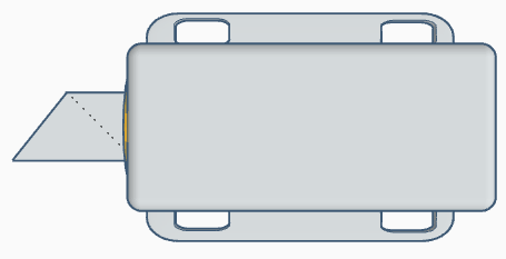
A 12V Solenoid Lock is an electromechanical device designed to control access through a locking mechanism. It operates by using an electrical current to generate a magnetic field, which in turn moves a plunger or bolt. When energized, the solenoid lock retracts the bolt, allowing the lock to open; when de-energized, a spring or gravity returns the bolt to its extended, locked position. This type of lock is commonly used in electronic door locks, vending machines, safety deposit boxes, and various other security applications.
Explore Projects Built with 12V Solenoid Lock
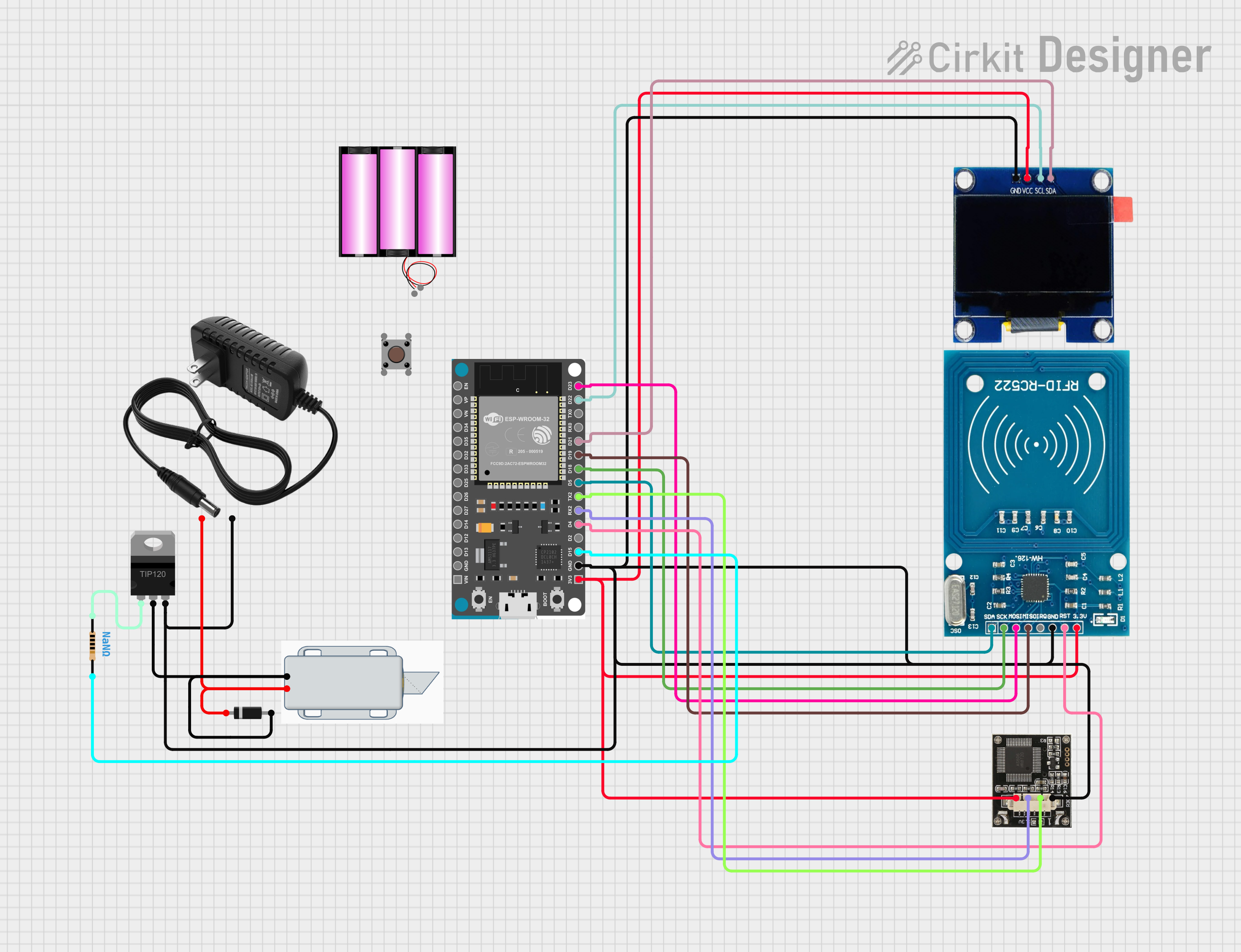
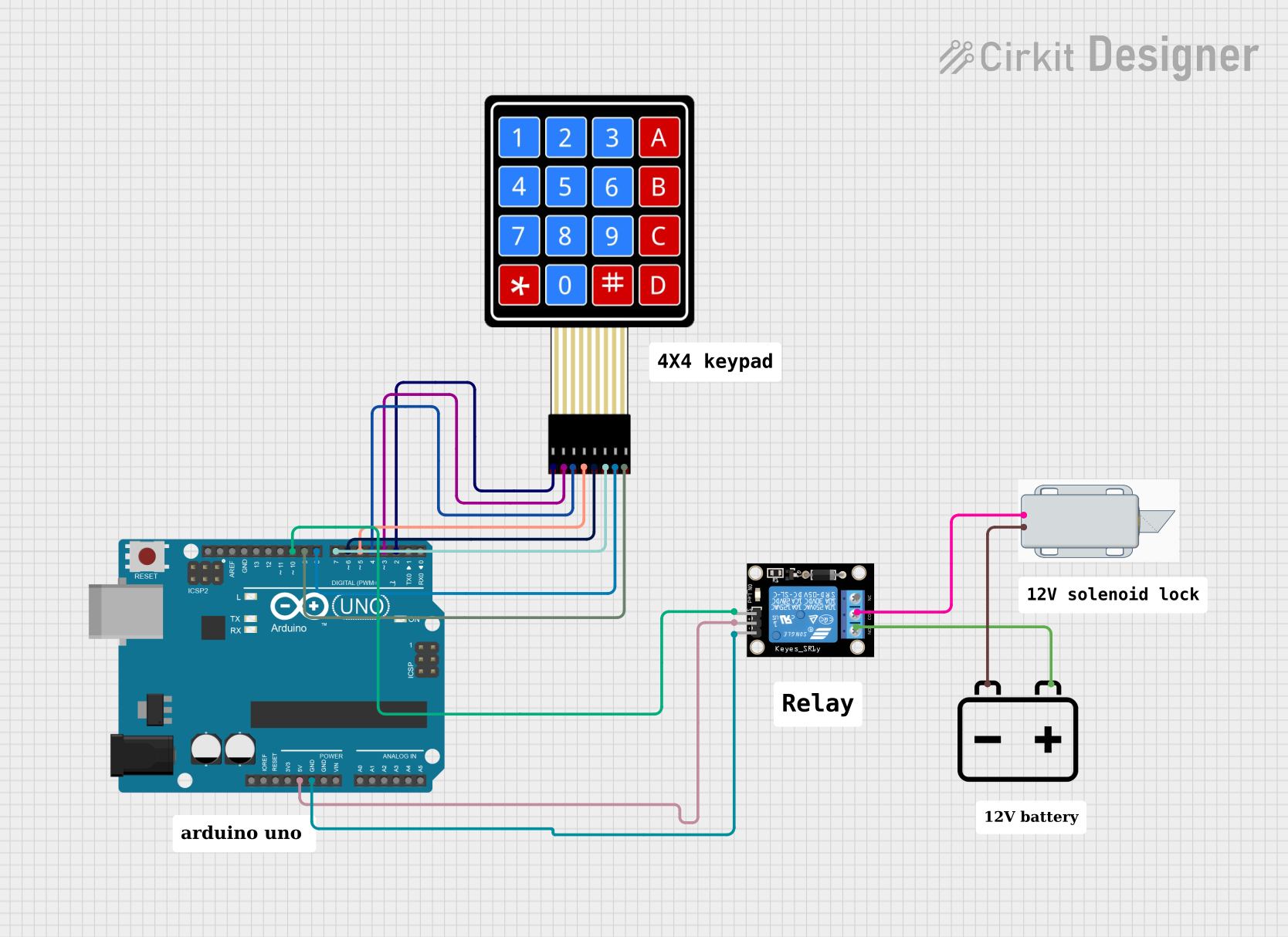
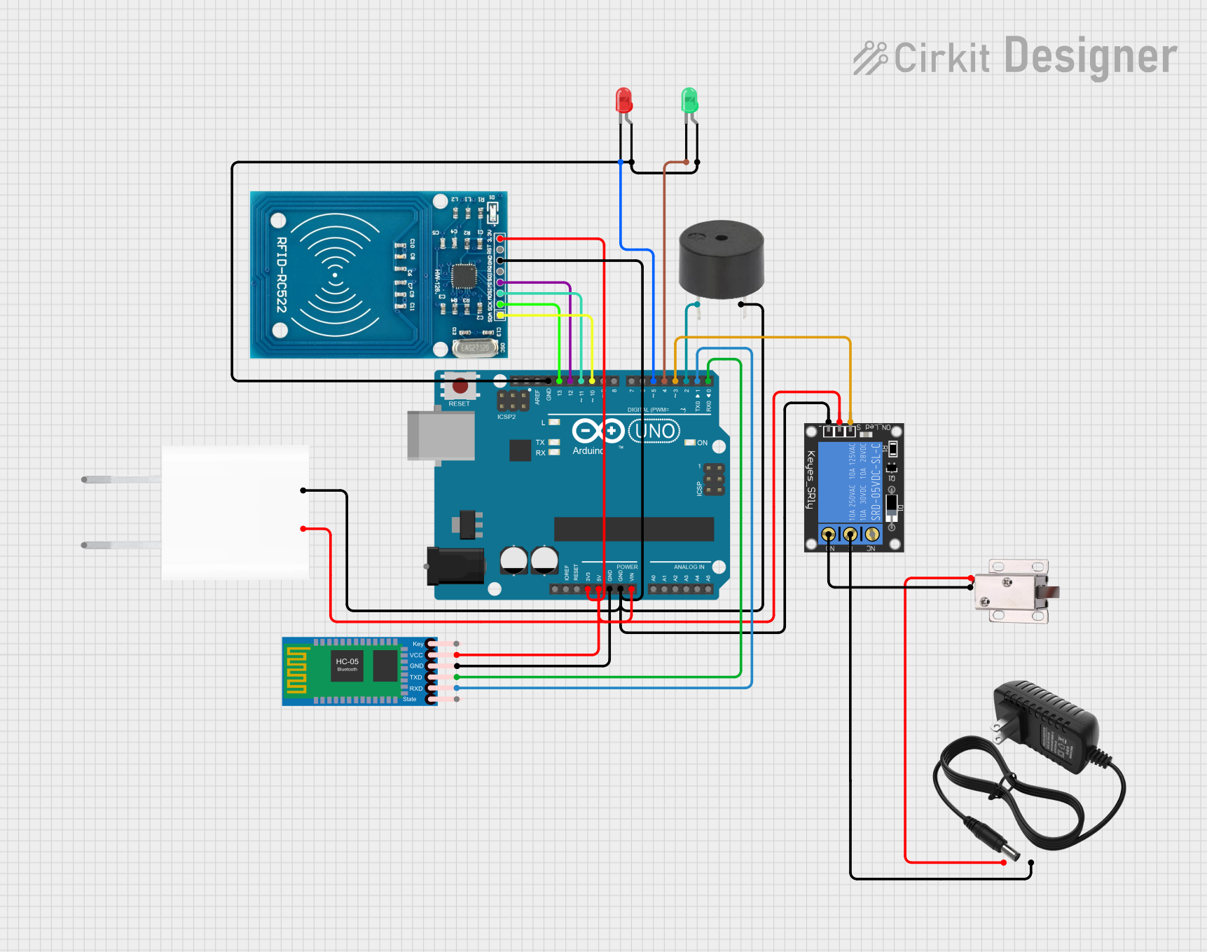
Explore Projects Built with 12V Solenoid Lock
Technical Specifications
Key Technical Details
- Operating Voltage: 12V DC
- Current Draw: Typically 1-2A (when active)
- Power Consumption: Approximately 12-24W (when active)
- Operation Mode: Fail-secure (remains locked if power is lost)
- Duty Cycle: Intermittent use recommended (not for continuous operation)
Pin Configuration and Descriptions
| Pin Number | Description | Notes |
|---|---|---|
| 1 | Positive Voltage (V+) | Connect to 12V power supply |
| 2 | Ground (GND) | Connect to power supply ground |
Usage Instructions
How to Use the Component in a Circuit
Power Supply Connection: Connect the positive terminal of a 12V power supply to Pin 1 of the solenoid lock. Connect the ground terminal of the power supply to Pin 2.
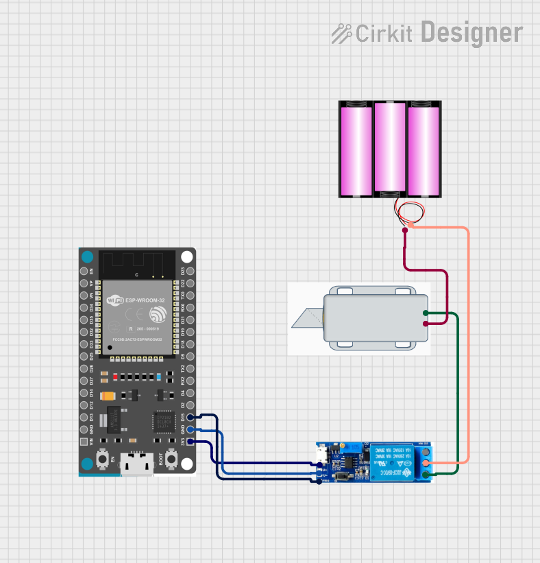
Control Mechanism: To control the solenoid lock, use a switch, relay, or a microcontroller like an Arduino UNO to provide power to the solenoid intermittently.
Mounting: Secure the solenoid lock to the desired surface, ensuring that the moving bolt can extend and retract without obstruction.
Important Considerations and Best Practices
- Power Rating: Ensure that the power supply can handle the current draw of the solenoid lock without overheating or shutting down.
- Heat Dissipation: Solenoids can get hot during operation; allow for proper ventilation and consider duty cycle to prevent overheating.
- Intermittent Use: To prolong the life of the solenoid lock, avoid continuous operation. Use it in applications where it is energized only for short periods.
- Safety: When installing the solenoid lock, ensure that it does not pose a safety hazard when transitioning between locked and unlocked states.
Example Arduino UNO Code
// Define the solenoid lock control pin
const int solenoidPin = 2;

void setup() {
  // Set the solenoid pin as an output
  pinMode(solenoidPin, OUTPUT);
}

void loop() {
  // Unlock the solenoid lock for 5 seconds
  digitalWrite(solenoidPin, HIGH);
  delay(5000);

  // Lock the solenoid lock
  digitalWrite(solenoidPin, LOW);
  delay(5000);
}
Note: The above code assumes the use of a relay or transistor to handle the current requirements of the solenoid lock. Direct connection to an Arduino pin is not recommended due to the high current draw of the solenoid.
Troubleshooting and FAQs
Common Issues
- Solenoid Lock Does Not Actuate: Check the power supply and connections. Ensure the voltage and current ratings are adequate.
- Overheating: If the solenoid lock is getting too hot, reduce the duty cycle or improve cooling.
- Intermittent Operation: Loose connections or insufficient power supply can cause unreliable operation.
Solutions and Tips for Troubleshooting
- Power Supply: Verify that the power supply is capable of delivering 12V at the required current without voltage drops.
- Connections: Ensure all connections are secure and free of corrosion.
- Cooling: Provide adequate ventilation around the solenoid lock. Consider adding a heat sink if necessary.
FAQs
Q: Can I operate the solenoid lock continuously? A: No, the solenoid lock is designed for intermittent use. Continuous operation can lead to overheating and reduced lifespan.
Q: What happens to the solenoid lock if the power is cut? A: This solenoid lock is fail-secure, meaning it will remain in the locked position if power is lost.
Q: Can I control the solenoid lock with a battery? A: Yes, as long as the battery can provide 12V and sufficient current for the operation of the solenoid lock.
Q: Is it possible to adjust the force of the solenoid lock? A: The force is generally fixed based on the design of the solenoid. However, operating voltage can slightly affect the force, within the acceptable voltage range.
This documentation provides a comprehensive guide to using a 12V Solenoid Lock. For further assistance, consult the manufacturer's datasheet or contact technical support.