
How to Use Dragino LoRa Shield V1.4: Examples, Pinouts, and Specs
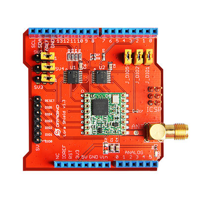
 Design with Dragino LoRa Shield V1.4 in Cirkit Designer
Introduction
The Dragino LoRa Shield V1.4 is a wireless communication module designed to enable long-range, low-power data transmission using LoRa (Long Range) technology. It is specifically built for Arduino and compatible boards, making it an excellent choice for IoT (Internet of Things) applications. This shield allows devices to communicate over distances of up to several kilometers while consuming minimal power, making it ideal for remote monitoring, smart agriculture, environmental sensing, and other IoT projects.
Explore Projects Built with Dragino LoRa Shield V1.4
 Open Project in Cirkit Designer
 Open Project in Cirkit Designer
 Open Project in Cirkit Designer
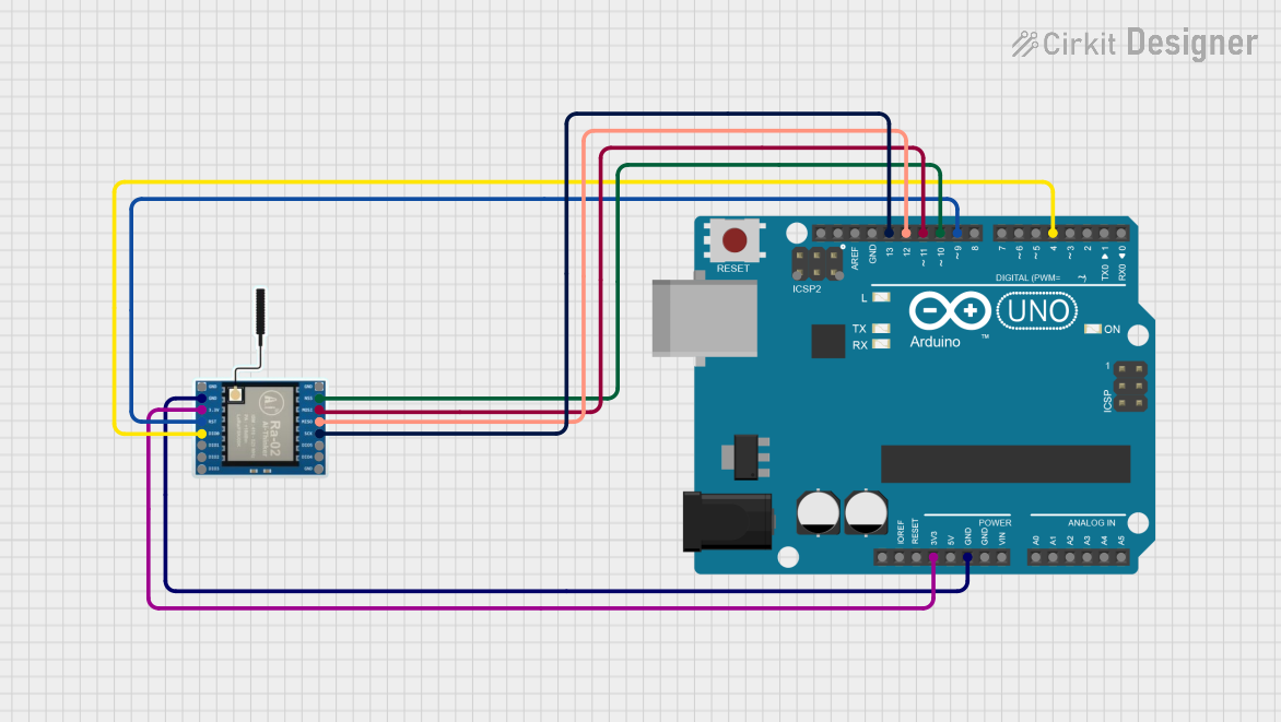 Open Project in Cirkit Designer
Explore Projects Built with Dragino LoRa Shield V1.4
Open Project in Cirkit DesignerOpen Project in Cirkit DesignerOpen Project in Cirkit DesignerOpen Project in Cirkit DesignerCommon Applications and Use Cases
- Smart agriculture (e.g., soil moisture monitoring)
- Environmental monitoring (e.g., air quality sensors)
- Industrial IoT (e.g., machine status reporting)
- Smart cities (e.g., parking sensors, streetlight control)
- Remote data logging and telemetry
Technical Specifications
The Dragino LoRa Shield V1.4 is based on the SX1276/SX1278 LoRa module and is compatible with Arduino boards. Below are the key technical details:
Key Technical Details
| Parameter | Specification |
|---|---|
| Frequency Range | 868 MHz (EU) / 915 MHz (US) |
| Modulation | LoRa (Long Range) |
| Communication Range | Up to 5 km (line of sight) |
| Power Supply Voltage | 3.3V or 5V (via Arduino) |
| Operating Current | 10 mA (typical) |
| Transmit Power | Up to 20 dBm |
| Sensitivity | -148 dBm |
| Interface | SPI |
| Dimensions | 68.6 mm x 53.4 mm |
Pin Configuration and Descriptions
The Dragino LoRa Shield V1.4 uses the SPI interface for communication with the Arduino. Below is the pin configuration:
| Pin Name | Arduino Pin Mapping | Description |
|---|---|---|
| MOSI | D11 | SPI Master Out Slave In |
| MISO | D12 | SPI Master In Slave Out |
| SCK | D13 | SPI Clock |
| NSS | D10 | SPI Chip Select |
| DIO0 | D2 | LoRa Interrupt Pin |
| DIO1 | D3 | Optional Interrupt Pin |
| RESET | D4 | LoRa Module Reset |
| 3.3V/5V | 3.3V/5V | Power Supply |
| GND | GND | Ground |
Usage Instructions
How to Use the Dragino LoRa Shield V1.4 in a Circuit
- Attach the Shield to an Arduino Board: Plug the Dragino LoRa Shield V1.4 directly onto an Arduino UNO or compatible board.
- Connect an Antenna: Attach a suitable antenna to the SMA connector on the shield to ensure proper signal transmission and reception.
- Install Required Libraries: Download and install the
LoRalibrary for Arduino from the Arduino IDE Library Manager. - Write and Upload Code: Use the Arduino IDE to write and upload code to the Arduino board for transmitting or receiving data.
- Power the Circuit: Power the Arduino board via USB or an external power source.
Important Considerations and Best Practices
- Antenna Selection: Always connect an antenna before powering the shield to avoid damage to the LoRa module.
- Frequency Compliance: Ensure that the operating frequency (868 MHz or 915 MHz) complies with local regulations.
- Power Supply: Use a stable power supply to avoid communication issues.
- SPI Pin Mapping: Verify the SPI pin mapping if using a non-standard Arduino board.
- Range Optimization: For maximum range, ensure a clear line of sight between the transmitter and receiver.
Example Code for Arduino UNO
Below is an example of how to use the Dragino LoRa Shield V1.4 to send a simple message:
#include <SPI.h>
#include <LoRa.h>

// Define LoRa pins for Dragino LoRa Shield
#define NSS 10    // SPI Chip Select
#define RESET 4   // LoRa Reset
#define DIO0 2    // LoRa Interrupt Pin

void setup() {
  // Initialize serial communication for debugging
  Serial.begin(9600);
  while (!Serial);

  Serial.println("Initializing LoRa...");

  // Initialize LoRa module with custom pin mapping
  if (!LoRa.begin(915E6)) { // Set frequency to 915 MHz
    Serial.println("LoRa initialization failed!");
    while (1);
  }

  Serial.println("LoRa initialized successfully!");
}

void loop() {
  // Send a test message
  Serial.println("Sending message...");
  LoRa.beginPacket();
  LoRa.print("Hello, LoRa!");
  LoRa.endPacket();

  // Wait for 5 seconds before sending the next message
  delay(5000);
}
Notes:
- Modify the frequency in
LoRa.begin(915E6)to match your region (e.g.,868E6for Europe). - Ensure the LoRa library is installed in the Arduino IDE.
Troubleshooting and FAQs
Common Issues and Solutions
LoRa Initialization Fails
- Cause: Incorrect wiring or frequency mismatch.
- Solution: Double-check the pin connections and ensure the frequency matches your region.
No Data Transmission
- Cause: Antenna not connected or poor signal conditions.
- Solution: Ensure the antenna is securely connected and check for obstructions in the signal path.
Short Communication Range
- Cause: Interference or improper antenna placement.
- Solution: Use a higher-gain antenna and ensure a clear line of sight between devices.
High Power Consumption
- Cause: Continuous transmission or incorrect power settings.
- Solution: Use sleep modes in your code to reduce power consumption during idle periods.
FAQs
Q: Can I use the Dragino LoRa Shield with boards other than Arduino UNO?
A: Yes, the shield is compatible with other Arduino boards, but you may need to adjust the SPI pin mapping in your code.
Q: What is the maximum range of the Dragino LoRa Shield?
A: The range can reach up to 5 km in line-of-sight conditions. However, obstacles and interference may reduce the range.
Q: Do I need an external power supply for the shield?
A: No, the shield is powered directly by the Arduino board.
Q: Can I use multiple LoRa shields in the same network?
A: Yes, you can use multiple shields, but ensure each device has a unique identifier in your code to avoid conflicts.
This concludes the documentation for the Dragino LoRa Shield V1.4.