How to Use SparkFun ESP8266 Thing: Examples, Pinouts, and Specs
Introduction
The SparkFun ESP8266 Thing is a versatile development board that harnesses the capabilities of the ESP8266 Wi-Fi module, enabling Wi-Fi connectivity for a wide range of projects. This board is particularly useful for Internet of Things (IoT) applications, wireless sensor networks, and any project requiring remote data communication. Its compact design and powerful onboard processing make it ideal for prototyping and small-scale production.
Explore Projects Built with SparkFun ESP8266 Thing
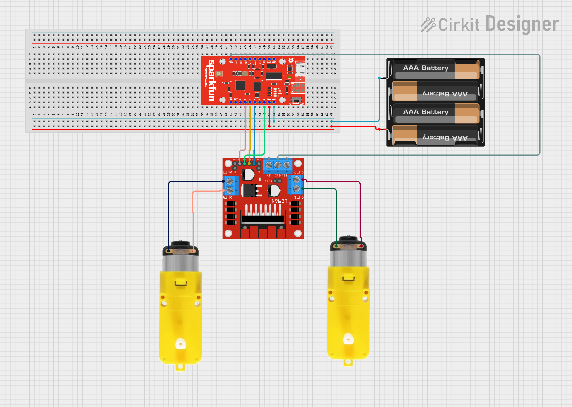
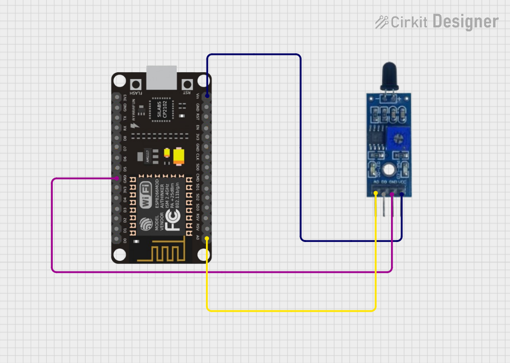


Explore Projects Built with SparkFun ESP8266 Thing
Common Applications and Use Cases
- IoT devices
- Home automation systems
- Wireless data logging
- Remote sensor monitoring
- Web servers for small-scale applications
Technical Specifications
Key Technical Details
- Microcontroller: ESP8266
- Operating Voltage: 3.3V
- Input Voltage: 4.5V - 12V (via raw pin) or 5V (via micro USB)
- Digital I/O Pins: 11
- Analog Input Pins: 1 (Max input: 1V)
- Flash Memory: 512KB (upgradable to 1MB)
- SRAM: 80KB
- Clock Speed: 80MHz (can be overclocked to 160MHz)
- Wi-Fi Standards: 802.11 b/g/n
- Wi-Fi Modes: AP, STA, AP+STA
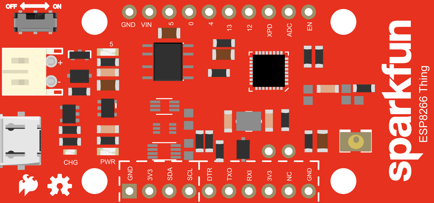
Pin Configuration and Descriptions
| Pin Number | Function | Description |
|---|---|---|
| 1 | TX | UART transmit |
| 2 | RX | UART receive |
| 3 | RST | Reset pin |
| 4 | CH_PD | Chip power-down |
| 5 | GPIO0 | General-purpose I/O and programming mode pin |
| 6 | GPIO2 | General-purpose I/O |
| 7 | GPIO4 | General-purpose I/O |
| 8 | GPIO5 | General-purpose I/O |
| 9 | GPIO12 | General-purpose I/O |
| 10 | GPIO13 | General-purpose I/O |
| 11 | GPIO14 | General-purpose I/O |
| 12 | GPIO15 | General-purpose I/O |
| 13 | GPIO16 | General-purpose I/O, deep sleep wake-up |
| 14 | A0 | Analog input |
| 15 | SDA | I2C data line |
| 16 | SCL | I2C clock line |
| 17 | VCC | 3.3V power supply |
| 18 | GND | Ground |
Usage Instructions
How to Use the Component in a Circuit
Powering the Board:
- Connect a stable 3.3V supply to the VCC and GND pins, or
- Power the board via the micro USB port.
Programming the Board:
- The ESP8266 Thing can be programmed via the Arduino IDE.
- Ensure that you have installed the necessary ESP8266 board package in the Arduino IDE.
- Select the correct board from the Tools > Board menu.
- Connect the board to your computer using a micro USB cable.
Connecting to Wi-Fi:
- Use the ESP8266WiFi library included with the ESP8266 board package to connect to a Wi-Fi network.
- Use the
WiFi.begin(ssid, password)function to initiate a connection.
Important Considerations and Best Practices
- Always use a 3.3V power supply for the VCC pin to avoid damaging the board.
- When programming, ensure GPIO0 is grounded to enable the bootloader mode.
- Avoid applying more than 1V to the analog input (A0) to prevent damage to the board.
- Use proper decoupling capacitors close to the power pins to minimize power supply noise.
Troubleshooting and FAQs
Common Issues
Board not connecting to Wi-Fi:
- Check the SSID and password.
- Ensure the board is within the range of the Wi-Fi router.
- Verify that the Wi-Fi network is 2.4 GHz as the ESP8266 does not support 5 GHz networks.
Board not recognized by the computer:
- Ensure the micro USB cable is data-capable.
- Check the USB port and try a different one if necessary.
- Restart the Arduino IDE and reconnect the board.
Unable to program the board:
- Make sure GPIO0 is grounded during the programming.
- Check the selected board and port in the Arduino IDE.
- Ensure the correct drivers are installed for the USB to UART bridge.
FAQs
Q: Can I use the ESP8266 Thing with a battery?
- A: Yes, you can power the board with a battery, but ensure it provides a stable 3.3V or use a voltage regulator.
Q: How do I update the firmware on the ESP8266?
- A: Firmware updates can be done through the Arduino IDE or using the esptool.py script with the appropriate firmware binary.
Q: What is the maximum current draw of the ESP8266 Thing?
- A: The ESP8266 can draw up to 300-400 mA during Wi-Fi transmissions. Ensure your power supply can handle this demand.
Example Code for Arduino UNO
#include <ESP8266WiFi.h>

const char* ssid     = "yourSSID"; // Replace with your network credentials
const char* password = "yourPASSWORD";

void setup() {
  Serial.begin(115200);
  // Connect to Wi-Fi
  WiFi.begin(ssid, password);
  while (WiFi.status() != WL_CONNECTED) {
    delay(500);
    Serial.print(".");
  }
  Serial.println("");
  Serial.println("WiFi connected.");
  Serial.println("IP address: ");
  Serial.println(WiFi.localIP());
}

void loop() {
  // Your code here
}
Remember to replace yourSSID and yourPASSWORD with your actual Wi-Fi network credentials. This code initializes the Wi-Fi connection and, once connected, prints the local IP address to the Serial Monitor.