Cirkit Designer Logo
Cirkit Designer
Your all-in-one circuit design IDE
Home / 
Component Documentation

How to Use Mosfet: Examples, Pinouts, and Specs

Image of Mosfet
Cirkit Designer LogoDesign with Mosfet in Cirkit Designer

Introduction

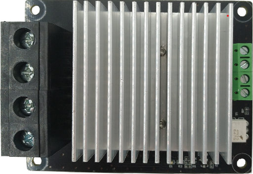
The MKS 3D-Drucker Mosfet is a high-performance Metal-Oxide-Semiconductor Field-Effect Transistor (MOSFET) designed for efficient switching and amplification of electronic signals. This component is widely used in power electronics, digital circuits, and 3D printer applications due to its high efficiency, fast switching capabilities, and ability to handle high currents.

Explore Projects Built with Mosfet

Use Cirkit Designer to design, explore, and prototype these projects online. Some projects support real-time simulation. Click "Open Project" to start designing instantly!
Arduino UNO Controlled Mosfet Switch with Power Supply and Diode Protection
Image of me3902stuff: A project utilizing Mosfet in a practical application
This circuit uses an Arduino UNO to control a MOSFET, which in turn regulates the current through a diode and a 15-ohm resistor. The Arduino outputs a signal to the gate of the MOSFET via a 10k-ohm resistor, allowing the MOSFET to switch the power supplied by an external power source to the diode and resistor.
Cirkit Designer LogoOpen Project in Cirkit Designer
ESP32-Controlled Motor with IRFZ44N MOSFET
Image of circit design: A project utilizing Mosfet in a practical application
This circuit uses an ESP32 microcontroller to control a motor through an IRFZ44N MOSFET. The ESP32's GPIO pin D21 is connected through a 10-ohm resistor to the gate of the MOSFET, which switches the motor on and off. A 10k-ohm pull-down resistor is connected to the gate to ensure the MOSFET turns off when the GPIO pin is not driving it, and the motor is powered by a 12V battery.
Cirkit Designer LogoOpen Project in Cirkit Designer
ESP32-Controlled Pneumatic Solenoid Valve with MOSFET Switching
Image of ESPooky32: A project utilizing Mosfet in a practical application
This circuit uses an ESP32 microcontroller to control a 12V pneumatic solenoid valve via an IRFZ44N MOSFET as a switch. The ESP32 outputs a control signal through a 220-ohm resistor to the gate of the MOSFET, which in turn controls the power to the solenoid valve from a 12V power supply. A 10k-ohm resistor provides a pull-down for the MOSFET gate to ensure it remains off when not driven by the ESP32.
Cirkit Designer LogoOpen Project in Cirkit Designer
Pixhawk-Controlled Solenoid Driver with Voltage Regulation
Image of solenoid control circuit: A project utilizing Mosfet in a practical application
This circuit uses an LM393 comparator to drive an IRFZ44N MOSFET based on the comparison between two input signals from a pixhawk 2.4.8 flight controller. The MOSFET switches a solenoid, with a diode for back EMF protection, and the system is powered by a Lipo battery with voltage regulation provided by a step-up boost converter and a step-down voltage regulator to ensure stable operation. A resistor is connected to the gate of the MOSFET for proper biasing.
Cirkit Designer LogoOpen Project in Cirkit Designer

Explore Projects Built with Mosfet

Use Cirkit Designer to design, explore, and prototype these projects online. Some projects support real-time simulation. Click "Open Project" to start designing instantly!
Image of me3902stuff: A project utilizing Mosfet in a practical application
Arduino UNO Controlled Mosfet Switch with Power Supply and Diode Protection
This circuit uses an Arduino UNO to control a MOSFET, which in turn regulates the current through a diode and a 15-ohm resistor. The Arduino outputs a signal to the gate of the MOSFET via a 10k-ohm resistor, allowing the MOSFET to switch the power supplied by an external power source to the diode and resistor.
Cirkit Designer LogoOpen Project in Cirkit Designer
Image of circit design: A project utilizing Mosfet in a practical application
ESP32-Controlled Motor with IRFZ44N MOSFET
This circuit uses an ESP32 microcontroller to control a motor through an IRFZ44N MOSFET. The ESP32's GPIO pin D21 is connected through a 10-ohm resistor to the gate of the MOSFET, which switches the motor on and off. A 10k-ohm pull-down resistor is connected to the gate to ensure the MOSFET turns off when the GPIO pin is not driving it, and the motor is powered by a 12V battery.
Cirkit Designer LogoOpen Project in Cirkit Designer
Image of ESPooky32: A project utilizing Mosfet in a practical application
ESP32-Controlled Pneumatic Solenoid Valve with MOSFET Switching
This circuit uses an ESP32 microcontroller to control a 12V pneumatic solenoid valve via an IRFZ44N MOSFET as a switch. The ESP32 outputs a control signal through a 220-ohm resistor to the gate of the MOSFET, which in turn controls the power to the solenoid valve from a 12V power supply. A 10k-ohm resistor provides a pull-down for the MOSFET gate to ensure it remains off when not driven by the ESP32.
Cirkit Designer LogoOpen Project in Cirkit Designer
Image of solenoid control circuit: A project utilizing Mosfet in a practical application
Pixhawk-Controlled Solenoid Driver with Voltage Regulation
This circuit uses an LM393 comparator to drive an IRFZ44N MOSFET based on the comparison between two input signals from a pixhawk 2.4.8 flight controller. The MOSFET switches a solenoid, with a diode for back EMF protection, and the system is powered by a Lipo battery with voltage regulation provided by a step-up boost converter and a step-down voltage regulator to ensure stable operation. A resistor is connected to the gate of the MOSFET for proper biasing.
Cirkit Designer LogoOpen Project in Cirkit Designer

Common Applications and Use Cases

  • Power control in 3D printers (e.g., heated beds, extruders)
  • Motor drivers and speed controllers
  • DC-DC converters and power supplies
  • High-speed switching in digital circuits
  • LED dimming and lighting control

Technical Specifications

The following table outlines the key technical details of the MKS 3D-Drucker Mosfet:

Parameter Value
Manufacturer MKS
Part ID 3D-Drucker Mosfet
Type N-Channel MOSFET
Maximum Voltage (Vds) 24V
Maximum Current (Id) 25A
Gate Threshold Voltage 2-4V
On-Resistance (Rds(on)) < 0.01Ω
Switching Speed Fast
Operating Temperature -55°C to +150°C
PCB Dimensions 60mm x 50mm x 20mm

Pin Configuration and Descriptions

The MKS 3D-Drucker Mosfet module typically has the following pin configuration:

Pin Name Description
VIN Input voltage (connect to the power source, e.g., 12V or 24V)
VOUT Output voltage (connect to the load, e.g., heated bed or motor)
GND Ground connection (common ground for the circuit)
Signal Control signal input (connect to the control board, e.g., Arduino or 3D printer)

Usage Instructions

How to Use the Component in a Circuit

  1. Power Connections:

    • Connect the VIN pin to the positive terminal of your power source (e.g., 12V or 24V).
    • Connect the GND pin to the ground of your power source and control board.
    • Connect the VOUT pin to the positive terminal of your load (e.g., heated bed, motor, or LED strip).
  2. Control Signal:

    • Connect the Signal pin to the control signal output of your microcontroller or 3D printer mainboard.
    • Ensure the control signal voltage is within the gate threshold voltage range (2-4V).
  3. Load Considerations:

    • Verify that the load does not exceed the maximum current rating of 25A.
    • Use appropriate heat dissipation methods (e.g., heatsinks or fans) if operating at high currents.

Important Considerations and Best Practices

  • Heat Management: The MOSFET can generate heat during operation. Use a heatsink or active cooling to prevent overheating.
  • Voltage Matching: Ensure the input voltage (VIN) matches the voltage requirements of your load.
  • Signal Voltage: The control signal voltage should be sufficient to fully turn on the MOSFET (above the gate threshold voltage).
  • Polarity: Double-check the polarity of all connections to avoid damage to the MOSFET or other components.

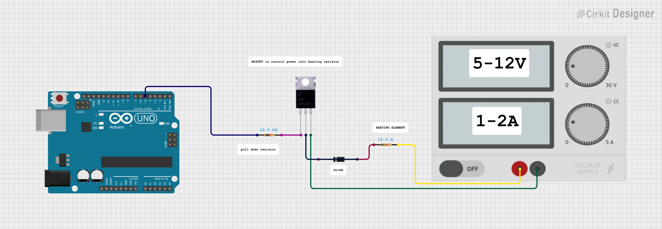
Example: Using the MOSFET with an Arduino UNO

Below is an example of how to control a 12V LED strip using the MKS 3D-Drucker Mosfet and an Arduino UNO:

Circuit Diagram

  • Connect the VIN pin to a 12V power supply.
  • Connect the VOUT pin to the positive terminal of the LED strip.
  • Connect the GND pin to the common ground of the Arduino and power supply.
  • Connect the Signal pin to a PWM-capable pin on the Arduino (e.g., Pin 9).

Arduino Code

// Example code to control a 12V LED strip using the MKS 3D-Drucker Mosfet
// Connect the Signal pin of the MOSFET to Arduino Pin 9

const int mosfetPin = 9; // Define the MOSFET control pin

void setup() {
  pinMode(mosfetPin, OUTPUT); // Set the MOSFET pin as an output
}

void loop() {
  analogWrite(mosfetPin, 128); // Set LED brightness to 50% (PWM value: 128)
  delay(1000);                 // Wait for 1 second
  analogWrite(mosfetPin, 255); // Set LED brightness to 100% (PWM value: 255)
  delay(1000);                 // Wait for 1 second
}

Troubleshooting and FAQs

Common Issues and Solutions

  1. MOSFET Overheating:

    • Cause: High current load or insufficient cooling.
    • Solution: Use a heatsink or active cooling (e.g., a fan) to dissipate heat.
  2. Load Not Turning On:

    • Cause: Insufficient control signal voltage or incorrect wiring.
    • Solution: Verify that the control signal voltage is above the gate threshold voltage (2-4V). Check all connections.
  3. MOSFET Not Switching Properly:

    • Cause: Signal pin not connected to a PWM-capable pin or incorrect signal voltage.
    • Solution: Ensure the Signal pin is connected to a PWM-capable pin on the microcontroller and the signal voltage is within the required range.
  4. Short Circuit:

    • Cause: Incorrect wiring or reversed polarity.
    • Solution: Double-check all connections and ensure correct polarity.

FAQs

  • Q: Can I use this MOSFET with a 24V power supply?

    • A: Yes, the MOSFET supports input voltages up to 24V.
  • Q: Do I need a heatsink for low-current applications?

    • A: For low-current applications (e.g., <5A), a heatsink may not be necessary. However, monitor the temperature during operation.
  • Q: Can I control this MOSFET with a 3.3V microcontroller?

    • A: Yes, as long as the control signal voltage is above the gate threshold voltage (2-4V).
  • Q: Is this MOSFET suitable for AC loads?

    • A: No, this MOSFET is designed for DC loads only. For AC loads, use a TRIAC or other suitable component.