Cirkit Designer Logo
Cirkit Designer
Your all-in-one circuit design IDE
Home / 
Component Documentation

How to Use zmct: Examples, Pinouts, and Specs

Image of zmct
Cirkit Designer LogoDesign with zmct in Cirkit Designer

Introduction

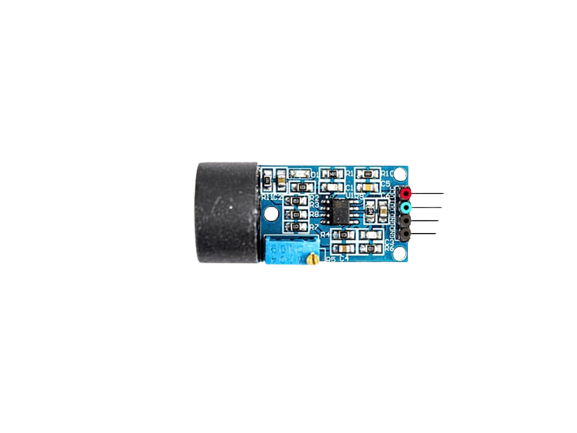
The ZMCT is a current sensor module designed to measure both AC and DC currents using a Hall effect sensor. It provides an isolated output, ensuring safety and reliability in applications where electrical isolation is critical. The ZMCT is compact, efficient, and widely used in various current measurement and monitoring systems.

Explore Projects Built with zmct

Use Cirkit Designer to design, explore, and prototype these projects online. Some projects support real-time simulation. Click "Open Project" to start designing instantly!
NFC-Enabled Access Control System with Time Logging
Image of doorlock: A project utilizing zmct in a practical application
This circuit is designed for access control with time tracking capabilities. It features an NFC/RFID reader for authentication, an RTC module (DS3231) for real-time clock functionality, and an OLED display for user interaction. A 12V relay controls a magnetic lock, which is activated upon successful NFC/RFID authentication, and a button switch is likely used for manual operation or input. The T8_S3 microcontroller serves as the central processing unit, interfacing with the NFC/RFID reader, RTC, OLED, and relay to manage the access control logic.
Cirkit Designer LogoOpen Project in Cirkit Designer
NFC-Enabled Access Control System with Real-Time Clock and OLED Display
Image of doorlock: A project utilizing zmct in a practical application
This circuit is designed as an access control system with time-tracking capabilities. It uses an NFC/RFID reader for authentication, a real-time clock for time-stamping events, and an OLED display for user interface, all controlled by a T8_S3 microcontroller. A relay module actuates a magnetic lock, and a button switch provides additional user input, with a switching power supply delivering the necessary voltages.
Cirkit Designer LogoOpen Project in Cirkit Designer
MakerEdu Creator with Bluetooth, IR Sensors, LCD Display, and Push Button Interaction
Image of MKL Distance Measurement: A project utilizing zmct in a practical application
This circuit features a MakerEdu Creator microcontroller board interfaced with two MKE-S11 IR Infrared Obstacle Avoidance Sensors, a MKE-M02 Push Button Tact Switch, a MKE-M15 Bluetooth module, and a MKE-M08 LCD2004 I2C display module. The push button is connected to a digital input for user interaction, while the IR sensors are likely used for detecting obstacles. The Bluetooth module enables wireless communication, and the LCD display provides a user interface for displaying information or statuses.
Cirkit Designer LogoOpen Project in Cirkit Designer
Solar-Powered STM32-Based Automation System with Matrix Keypad and RTC
Image of soloar cleaner : A project utilizing zmct in a practical application
This circuit features an STM32F103C8T6 microcontroller interfaced with a membrane matrix keypad for input, an RTC DS3231 for real-time clock functionality, and a 16x2 I2C LCD for display. It controls four 12V geared motors through two MD20 CYTRON motor drivers, with the motor power supplied by a 12V battery regulated by a buck converter. The battery is charged via a solar panel connected through a solar charge controller, ensuring a renewable energy source for the system.
Cirkit Designer LogoOpen Project in Cirkit Designer

Explore Projects Built with zmct

Use Cirkit Designer to design, explore, and prototype these projects online. Some projects support real-time simulation. Click "Open Project" to start designing instantly!
Image of doorlock: A project utilizing zmct in a practical application
NFC-Enabled Access Control System with Time Logging
This circuit is designed for access control with time tracking capabilities. It features an NFC/RFID reader for authentication, an RTC module (DS3231) for real-time clock functionality, and an OLED display for user interaction. A 12V relay controls a magnetic lock, which is activated upon successful NFC/RFID authentication, and a button switch is likely used for manual operation or input. The T8_S3 microcontroller serves as the central processing unit, interfacing with the NFC/RFID reader, RTC, OLED, and relay to manage the access control logic.
Cirkit Designer LogoOpen Project in Cirkit Designer
Image of doorlock: A project utilizing zmct in a practical application
NFC-Enabled Access Control System with Real-Time Clock and OLED Display
This circuit is designed as an access control system with time-tracking capabilities. It uses an NFC/RFID reader for authentication, a real-time clock for time-stamping events, and an OLED display for user interface, all controlled by a T8_S3 microcontroller. A relay module actuates a magnetic lock, and a button switch provides additional user input, with a switching power supply delivering the necessary voltages.
Cirkit Designer LogoOpen Project in Cirkit Designer
Image of MKL Distance Measurement: A project utilizing zmct in a practical application
MakerEdu Creator with Bluetooth, IR Sensors, LCD Display, and Push Button Interaction
This circuit features a MakerEdu Creator microcontroller board interfaced with two MKE-S11 IR Infrared Obstacle Avoidance Sensors, a MKE-M02 Push Button Tact Switch, a MKE-M15 Bluetooth module, and a MKE-M08 LCD2004 I2C display module. The push button is connected to a digital input for user interaction, while the IR sensors are likely used for detecting obstacles. The Bluetooth module enables wireless communication, and the LCD display provides a user interface for displaying information or statuses.
Cirkit Designer LogoOpen Project in Cirkit Designer
Image of soloar cleaner : A project utilizing zmct in a practical application
Solar-Powered STM32-Based Automation System with Matrix Keypad and RTC
This circuit features an STM32F103C8T6 microcontroller interfaced with a membrane matrix keypad for input, an RTC DS3231 for real-time clock functionality, and a 16x2 I2C LCD for display. It controls four 12V geared motors through two MD20 CYTRON motor drivers, with the motor power supplied by a 12V battery regulated by a buck converter. The battery is charged via a solar panel connected through a solar charge controller, ensuring a renewable energy source for the system.
Cirkit Designer LogoOpen Project in Cirkit Designer

Common Applications and Use Cases

  • Power monitoring and energy management systems
  • Overcurrent protection in electrical circuits
  • Industrial automation and control systems
  • Battery management systems (BMS)
  • Smart home devices and IoT applications

Technical Specifications

Below are the key technical details of the ZMCT current sensor module:

Parameter Value
Measurement Type AC and DC current
Input Current Range 0A to 5A (typical)
Output Voltage Range 0V to 5V (proportional to input)
Supply Voltage 5V DC
Isolation Voltage Up to 2kV
Accuracy ±1% (typical)
Operating Temperature -40°C to +85°C
Dimensions Compact module (varies by model)

Pin Configuration and Descriptions

The ZMCT module typically has the following pinout:

Pin Name Description
1 VCC Power supply input (5V DC)
2 GND Ground connection
3 OUT Analog output voltage proportional to the measured current
4 NC (optional) Not connected (may vary depending on the specific ZMCT model)

Usage Instructions

How to Use the ZMCT in a Circuit

  1. Power the Module: Connect the VCC pin to a 5V DC power supply and the GND pin to the ground of your circuit.
  2. Connect the Load: Pass the wire carrying the current to be measured through the sensor's core (the hole in the module).
  3. Read the Output: The OUT pin provides an analog voltage proportional to the current passing through the sensor. This output can be read using an ADC (Analog-to-Digital Converter) on a microcontroller, such as an Arduino.

Important Considerations and Best Practices

  • Calibration: The ZMCT module may require calibration to ensure accurate current measurements. Use a known current source to determine the relationship between the output voltage and the input current.
  • Isolation: Ensure proper electrical isolation between the high-current side and the low-voltage side of the circuit.
  • Filtering: Add a capacitor (e.g., 0.1µF) across the output to filter noise and stabilize the signal.
  • Current Range: Do not exceed the specified current range of the module to avoid damage or inaccurate readings.

Example: Using the ZMCT with an Arduino UNO

Below is an example of how to interface the ZMCT with an Arduino UNO to measure current:

// ZMCT Current Sensor Example with Arduino UNO
// This code reads the analog output of the ZMCT sensor and calculates the current.

const int sensorPin = A0;  // Connect ZMCT OUT pin to Arduino analog pin A0
const float sensitivity = 0.185; // Sensitivity in V/A (example value, check your module's datasheet)
const float vRef = 5.0;    // Reference voltage of Arduino (5V for most boards)
const int adcResolution = 1024; // ADC resolution (10-bit for Arduino UNO)

void setup() {
  Serial.begin(9600); // Initialize serial communication for debugging
}

void loop() {
  int sensorValue = analogRead(sensorPin); // Read the analog value from the sensor
  float voltage = (sensorValue * vRef) / adcResolution; // Convert ADC value to voltage
  float current = voltage / sensitivity; // Calculate current based on sensor sensitivity

  // Print the measured current to the Serial Monitor
  Serial.print("Current: ");
  Serial.print(current);
  Serial.println(" A");

  delay(1000); // Wait for 1 second before the next reading
}

Notes:

  • Replace the sensitivity value with the actual sensitivity of your ZMCT module (refer to the datasheet).
  • Ensure proper wiring and connections to avoid inaccurate readings or damage to the module.

Troubleshooting and FAQs

Common Issues and Solutions

  1. No Output Signal:

    • Cause: Incorrect wiring or no current passing through the sensor.
    • Solution: Verify the connections and ensure the wire carrying the current passes through the sensor's core.
  2. Inaccurate Readings:

    • Cause: Calibration not performed or incorrect sensitivity value used.
    • Solution: Calibrate the sensor using a known current source and update the sensitivity value in your code.
  3. Noisy Output:

    • Cause: Electrical noise or insufficient filtering.
    • Solution: Add a capacitor (e.g., 0.1µF) across the output to filter noise.
  4. Overheating:

    • Cause: Current exceeding the module's rated range.
    • Solution: Ensure the current passing through the sensor is within the specified range.

FAQs

Q1: Can the ZMCT measure both AC and DC currents?
A1: Yes, the ZMCT is capable of measuring both AC and DC currents.

Q2: What is the maximum current the ZMCT can measure?
A2: The maximum current depends on the specific model, but it is typically up to 5A. Refer to the datasheet for exact details.

Q3: Is the ZMCT output linear?
A3: Yes, the output voltage is linearly proportional to the input current within the specified range.

Q4: Can I use the ZMCT with a 3.3V microcontroller?
A4: Yes, but ensure the output voltage does not exceed the ADC input range of your microcontroller. You may need a voltage divider or level shifter.

By following this documentation, you can effectively integrate the ZMCT current sensor module into your projects for accurate and reliable current measurement.