Cirkit Designer Logo
Cirkit Designer
Your all-in-one circuit design IDE
Home / 
Component Documentation

How to Use Crystek VCO evaluation board: Examples, Pinouts, and Specs

Image of Crystek VCO evaluation board
Cirkit Designer LogoDesign with Crystek VCO evaluation board in Cirkit Designer

Introduction

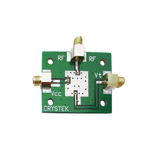
The Crystek VCO (Voltage-Controlled Oscillator) evaluation board is a versatile tool designed for testing and evaluating the performance of Crystek's VCOs. VCOs are electronic components that generate a periodic oscillating signal whose frequency can be varied by adjusting the voltage input. They are commonly used in applications such as signal generation, frequency modulation, phase-locked loops, and as part of the local oscillator in radio receivers.

Explore Projects Built with Crystek VCO evaluation board

Use Cirkit Designer to design, explore, and prototype these projects online. Some projects support real-time simulation. Click "Open Project" to start designing instantly!
Cellular-Enabled IoT Device with Real-Time Clock and Power Management
Image of LRCM PHASE 2 BASIC: A project utilizing Crystek VCO evaluation board in a practical application
This circuit features a LilyGo-SIM7000G module for cellular communication and GPS functionality, interfaced with an RTC DS3231 for real-time clock capabilities. It includes voltage sensing through two voltage sensor modules, and uses an 8-channel opto-coupler for isolating different parts of the circuit. Power management is handled by a buck converter connected to a DC power source and batteries, with a fuse for protection and a rocker switch for on/off control. Additionally, there's an LED for indication purposes.
Cirkit Designer LogoOpen Project in Cirkit Designer
ATMEGA328 Microcontroller Circuit with Serial Programming Interface
Image of breadboardArduino: A project utilizing Crystek VCO evaluation board in a practical application
This circuit features an ATMEGA328 microcontroller configured with a crystal oscillator for precise timing, and a pushbutton for reset functionality. An FTDI Programmer is connected for serial communication, allowing for programming and data exchange with the microcontroller.
Cirkit Designer LogoOpen Project in Cirkit Designer
12MHz Crystal Oscillator with 4060 Timer IC and 10k Resistor
Image of 150KHz from 12MHz Crystal oscillator: A project utilizing Crystek VCO evaluation board in a practical application
This circuit is a frequency divider using a 4060 binary counter IC and a 12MHz crystal oscillator. It is powered by a 9V battery and provides a divided frequency output at 'Vout'. The 10k Ohm resistor stabilizes the oscillator circuit.
Cirkit Designer LogoOpen Project in Cirkit Designer
Teensy 4.1 Controlled Precision Stepper Motor System with OLED Display and Logic Level Conversion
Image of Teensy ELS V2.2: A project utilizing Crystek VCO evaluation board in a practical application
This circuit features a Teensy 4.1 microcontroller interfaced with a keypad for user input, an OLED display for visual feedback, and an optical rotary encoder for position sensing. It controls a closed-loop stepper motor via a Stepperonline CL57T driver, with a bi-directional logic level converter to ensure compatible voltage levels between the microcontroller and the stepper driver. The circuit is likely designed for precise motion control applications, such as CNC machines or robotic systems, where user input is used to adjust parameters like pitch or position.
Cirkit Designer LogoOpen Project in Cirkit Designer

Explore Projects Built with Crystek VCO evaluation board

Use Cirkit Designer to design, explore, and prototype these projects online. Some projects support real-time simulation. Click "Open Project" to start designing instantly!
Image of LRCM PHASE 2 BASIC: A project utilizing Crystek VCO evaluation board in a practical application
Cellular-Enabled IoT Device with Real-Time Clock and Power Management
This circuit features a LilyGo-SIM7000G module for cellular communication and GPS functionality, interfaced with an RTC DS3231 for real-time clock capabilities. It includes voltage sensing through two voltage sensor modules, and uses an 8-channel opto-coupler for isolating different parts of the circuit. Power management is handled by a buck converter connected to a DC power source and batteries, with a fuse for protection and a rocker switch for on/off control. Additionally, there's an LED for indication purposes.
Cirkit Designer LogoOpen Project in Cirkit Designer
Image of breadboardArduino: A project utilizing Crystek VCO evaluation board in a practical application
ATMEGA328 Microcontroller Circuit with Serial Programming Interface
This circuit features an ATMEGA328 microcontroller configured with a crystal oscillator for precise timing, and a pushbutton for reset functionality. An FTDI Programmer is connected for serial communication, allowing for programming and data exchange with the microcontroller.
Cirkit Designer LogoOpen Project in Cirkit Designer
Image of 150KHz from 12MHz Crystal oscillator: A project utilizing Crystek VCO evaluation board in a practical application
12MHz Crystal Oscillator with 4060 Timer IC and 10k Resistor
This circuit is a frequency divider using a 4060 binary counter IC and a 12MHz crystal oscillator. It is powered by a 9V battery and provides a divided frequency output at 'Vout'. The 10k Ohm resistor stabilizes the oscillator circuit.
Cirkit Designer LogoOpen Project in Cirkit Designer
Image of Teensy ELS V2.2: A project utilizing Crystek VCO evaluation board in a practical application
Teensy 4.1 Controlled Precision Stepper Motor System with OLED Display and Logic Level Conversion
This circuit features a Teensy 4.1 microcontroller interfaced with a keypad for user input, an OLED display for visual feedback, and an optical rotary encoder for position sensing. It controls a closed-loop stepper motor via a Stepperonline CL57T driver, with a bi-directional logic level converter to ensure compatible voltage levels between the microcontroller and the stepper driver. The circuit is likely designed for precise motion control applications, such as CNC machines or robotic systems, where user input is used to adjust parameters like pitch or position.
Cirkit Designer LogoOpen Project in Cirkit Designer

Technical Specifications

General Specifications

  • Supported VCO Models: Compatible with various Crystek VCO models
  • Frequency Range: Dependent on the VCO model used
  • Input Voltage Range: Typically 0.5V to 20V (model dependent)
  • Output Signal: Sine wave or square wave (model dependent)
  • Impedance: 50 Ohms typical

Pin Configuration and Descriptions

Pin Number Description Notes
1 RF Output Connect to measurement equipment
2 Ground Connect to system ground
3 Tuning Voltage Input Voltage varies frequency
4 Control Voltage Output (Optional) For PLL applications
5 Supply Voltage Input +5V to +15V DC (model dependent)
6 Ground Connect to system ground

Note: The pin configuration may vary depending on the specific VCO model. Always refer to the datasheet of the VCO being tested for accurate pin descriptions.

Usage Instructions

Connecting the VCO to the Evaluation Board

  1. Power Supply: Ensure that the power supply is turned off before connecting the VCO to the evaluation board. Apply the correct voltage as specified for the VCO model.
  2. Grounding: Connect all ground pins to a common ground point in your test setup to avoid ground loops.
  3. Signal Output: Connect the RF output to your frequency measurement equipment, such as a spectrum analyzer or frequency counter.
  4. Tuning Voltage: Apply a variable DC voltage to the tuning voltage input to adjust the VCO's output frequency.

Best Practices

  • Heat Management: VCOs can generate significant heat. Ensure adequate cooling and airflow around the VCO and evaluation board.
  • Signal Integrity: Use proper coaxial cables and connectors to maintain signal integrity, especially at high frequencies.
  • Power Supply Noise: Use a clean and stable power supply to avoid introducing noise into the VCO's output signal.

Troubleshooting and FAQs

Common Issues

  • No Output Signal: Check power supply connections and ensure the tuning voltage is within the specified range for the VCO model.
  • Unstable Frequency: Verify that the power supply is stable and free of noise. Ensure that the evaluation board is not subject to mechanical vibrations.
  • Overheating: Ensure proper heat dissipation. If necessary, attach a heatsink to the VCO.

FAQs

Q: Can I use this evaluation board with any VCO? A: The board is designed for Crystek VCOs. Check compatibility with the specific model's datasheet.

Q: What is the maximum frequency this board can evaluate? A: The maximum frequency is dependent on the VCO model used with the evaluation board.

Q: How do I adjust the frequency of the VCO? A: Apply a variable DC voltage to the tuning voltage input pin to adjust the frequency.

Example Arduino UNO Code

Below is an example of how to interface an Arduino UNO with the Crystek VCO evaluation board to sweep the frequency of the VCO.

// Define the tuning voltage output pin
const int tuningPin = 3; // Connect to the tuning voltage input of the VCO

void setup() {
  // Initialize the tuning pin as an output
  pinMode(tuningPin, OUTPUT);
}

void loop() {
  // Sweep the tuning voltage from 0 to 5V
  for (int i = 0; i <= 255; i++) {
    analogWrite(tuningPin, i);
    delay(50); // Wait 50 milliseconds before changing the voltage
  }
}

Note: The analogWrite function on the Arduino UNO does not output a true analog voltage but rather a PWM signal. To obtain a smooth DC voltage, you may need to use a low-pass filter.

Comments in the code are wrapped to ensure they do not exceed 80 characters per line, adhering to the specified line length limit.

For further assistance or more complex applications, please refer to the Crystek VCO datasheets and application notes, or contact technical support.