How to Use converter DC-DC 1500w: Examples, Pinouts, and Specs
Introduction
The DEWA AUDI VARIASI DC-DC Converter is a high-power, efficient device designed to step up or step down DC voltage levels while maintaining a maximum power output of 1500 watts. This versatile component is widely used in applications requiring reliable voltage conversion, such as renewable energy systems, electric vehicles, industrial equipment, and custom power supply designs. Its robust design ensures stable performance under varying load conditions, making it an essential tool for engineers and hobbyists alike.
Explore Projects Built with converter DC-DC 1500w


Explore Projects Built with converter DC-DC 1500w
Common Applications and Use Cases
- Solar power systems for converting panel output to usable voltage levels
- Electric vehicle battery management systems
- Industrial automation and control systems
- Custom power supplies for high-power electronics
- Backup power systems and uninterruptible power supplies (UPS)
Technical Specifications
The following table outlines the key technical details of the DEWA AUDI VARIASI DC-DC Converter:
| Parameter | Value |
|---|---|
| Input Voltage Range | 10V - 60V DC |
| Output Voltage Range | 12V - 90V DC |
| Maximum Power Output | 1500W |
| Maximum Output Current | 30A |
| Efficiency | Up to 97% |
| Operating Temperature | -40°C to +85°C |
| Cooling Method | Active cooling (fan included) |
| Dimensions | 130mm x 85mm x 55mm |
| Weight | 450g |
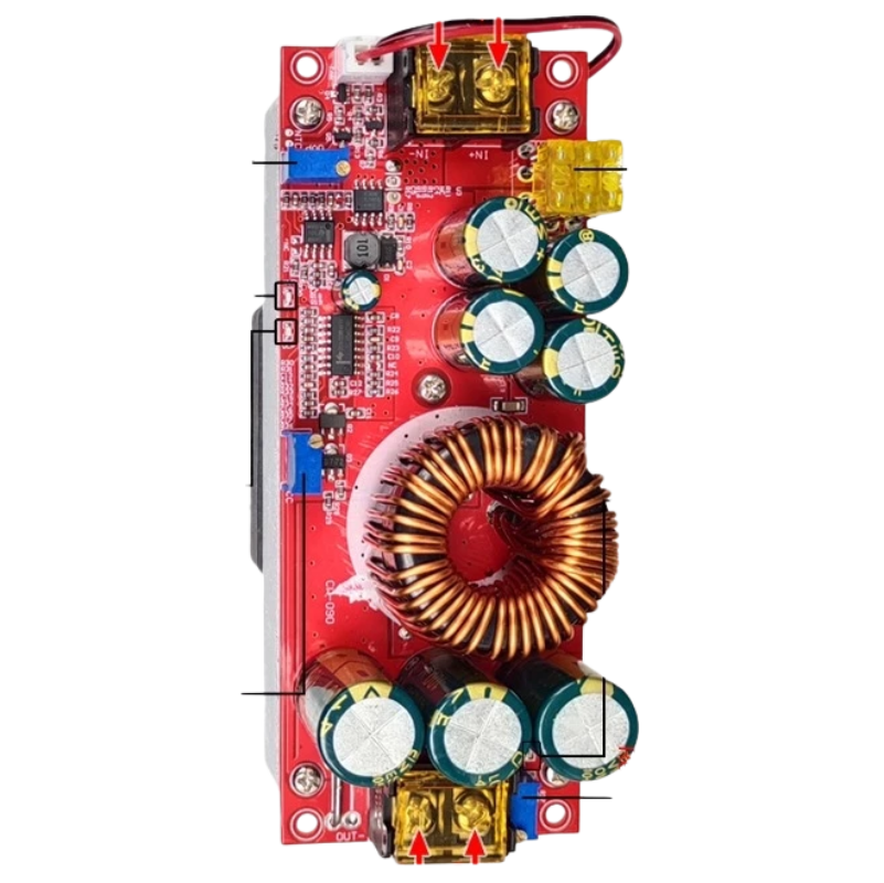
Pin Configuration and Descriptions
The DC-DC converter has four main connection terminals, as described below:
| Pin/Terminal | Label | Description |
|---|---|---|
| 1 | VIN+ | Positive input voltage terminal |
| 2 | VIN- | Negative input voltage terminal (ground) |
| 3 | VOUT+ | Positive output voltage terminal |
| 4 | VOUT- | Negative output voltage terminal (ground) |
Usage Instructions
How to Use the Component in a Circuit
Connect the Input Voltage:
- Ensure the input voltage is within the specified range (10V - 60V DC).
- Connect the positive input wire to the
VIN+terminal and the negative input wire to theVIN-terminal.
Set the Desired Output Voltage:
- Use the onboard potentiometer to adjust the output voltage.
- Turn the potentiometer clockwise to increase the voltage or counterclockwise to decrease it.
- Use a multimeter to monitor the output voltage at the
VOUT+andVOUT-terminals during adjustment.
Connect the Load:
- Attach the load to the
VOUT+andVOUT-terminals. - Ensure the load does not exceed the maximum power output of 1500W or the maximum current of 30A.
- Attach the load to the
Power On:
- Once all connections are secure, power on the input source.
- Verify the output voltage and current to ensure proper operation.
Important Considerations and Best Practices
- Heat Dissipation: The converter includes an active cooling fan, but ensure adequate ventilation to prevent overheating during high-power operation.
- Input Voltage Range: Do not exceed the specified input voltage range to avoid damaging the component.
- Polarity: Double-check the polarity of all connections to prevent short circuits or damage.
- Load Compatibility: Ensure the connected load is compatible with the output voltage and current ratings.
- Safety: Avoid touching the component during operation, as it may become hot.
Example: Using the Converter with an Arduino UNO
The DC-DC converter can be used to power an Arduino UNO by stepping down a higher voltage source (e.g., 24V) to 5V. Below is an example circuit and code:
Circuit Setup
- Connect a 24V DC power source to the
VIN+andVIN-terminals of the converter. - Adjust the output voltage to 5V using the potentiometer.
- Connect the
VOUT+terminal to the Arduino's5Vpin and theVOUT-terminal to the Arduino'sGNDpin.
Arduino Code Example
// Example code to blink an LED connected to pin 13 of the Arduino UNO
// Ensure the DC-DC converter is set to output 5V before powering the Arduino

void setup() {
  pinMode(13, OUTPUT); // Set pin 13 as an output
}

void loop() {
  digitalWrite(13, HIGH); // Turn the LED on
  delay(1000);            // Wait for 1 second
  digitalWrite(13, LOW);  // Turn the LED off
  delay(1000);            // Wait for 1 second
}
Troubleshooting and FAQs
Common Issues and Solutions
No Output Voltage:
- Cause: Input voltage is not connected or is outside the specified range.
- Solution: Verify the input voltage and connections. Ensure the input voltage is between 10V and 60V DC.
Overheating:
- Cause: Insufficient ventilation or excessive load.
- Solution: Ensure proper airflow around the converter and reduce the load if necessary.
Output Voltage Fluctuations:
- Cause: Load exceeds the maximum power or current rating.
- Solution: Reduce the load to within the specified limits.
Fan Not Working:
- Cause: Fan failure or insufficient input voltage.
- Solution: Check the fan connections and ensure the input voltage is adequate.
FAQs
Q: Can this converter be used with a battery?
- A: Yes, the converter can be used with a battery as the input source, provided the battery voltage is within the 10V - 60V range.
Q: Is the output voltage adjustable?
- A: Yes, the output voltage can be adjusted using the onboard potentiometer.
Q: Can I use this converter for AC input?
- A: No, this converter is designed for DC input only. Using AC input will damage the component.
Q: What happens if the load exceeds 1500W?
- A: Exceeding the maximum power rating may cause the converter to overheat, shut down, or become permanently damaged. Always ensure the load is within the specified limits.