
How to Use Analog Digital MUX Breakout: Examples, Pinouts, and Specs
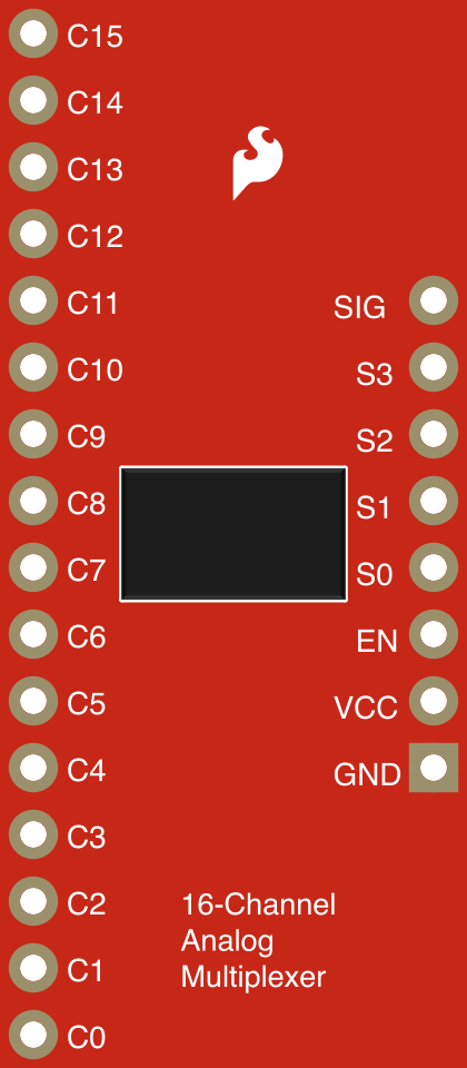
 Design with Analog Digital MUX Breakout in Cirkit Designer
Introduction
The Analog Digital MUX Breakout (SparkFun Part ID: BOB-09056) is a versatile breakout board designed to simplify signal routing in electronic circuits. It features a multiplexer (MUX) that allows users to select between multiple analog or digital signals, making it ideal for applications requiring efficient signal management. This component is particularly useful in projects involving microcontrollers, where limited input/output pins need to handle multiple signals.
Explore Projects Built with Analog Digital MUX Breakout
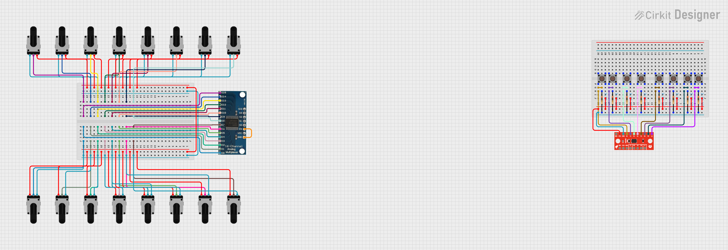 Open Project in Cirkit Designer
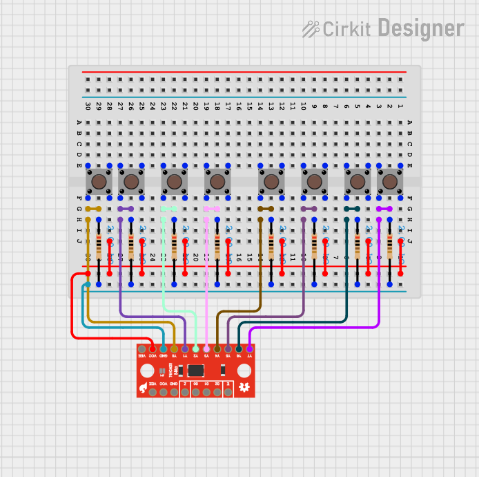 Open Project in Cirkit Designer
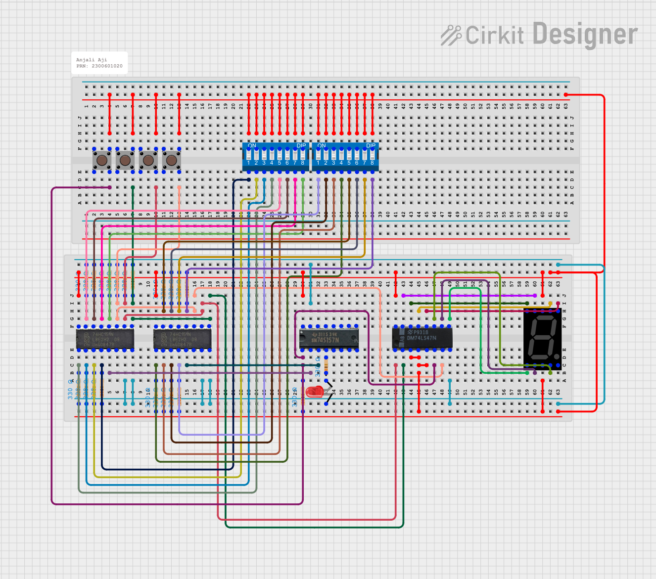 Open Project in Cirkit Designer
 Open Project in Cirkit Designer
Explore Projects Built with Analog Digital MUX Breakout
Open Project in Cirkit DesignerOpen Project in Cirkit DesignerOpen Project in Cirkit DesignerOpen Project in Cirkit DesignerCommon Applications and Use Cases
- Expanding the number of analog or digital inputs for microcontrollers
- Signal selection in sensor arrays
- Audio signal routing
- Data acquisition systems
- Prototyping and testing circuits with multiple signal sources
Technical Specifications
The Analog Digital MUX Breakout is based on the 74HC4051 multiplexer IC, which supports up to 8 channels of signal selection. Below are the key technical details:
Key Specifications
| Parameter | Value |
|---|---|
| Operating Voltage | 2V to 6V |
| Logic Level Compatibility | 3.3V and 5V |
| Signal Channels | 8 (1 of 8 multiplexer) |
| Signal Type | Analog or Digital |
| Maximum Signal Voltage | VCC (up to 6V) |
| Maximum Signal Frequency | 6 MHz (typical for digital signals) |
| Current Consumption | ~80 µA (at 5V) |
| PCB Dimensions | 0.7" x 0.7" (17.8mm x 17.8mm) |
Pin Configuration and Descriptions
The breakout board provides easy access to the 74HC4051 pins via labeled headers. Below is the pinout:
| Pin Name | Description |
|---|---|
| VCC | Power supply input (2V to 6V). Connect to the microcontroller's power pin. |
| GND | Ground connection. |
| SIG | Common signal pin (connects to the selected channel). |
| S0 | Selection pin 0 (LSB of the channel selector). |
| S1 | Selection pin 1. |
| S2 | Selection pin 2 (MSB of the channel selector). |
| C0-C7 | Channel pins (C0 to C7). Connect your signals to these pins. |
| EN | Enable pin (active LOW). Pull LOW to enable the MUX, HIGH to disable it. |
Usage Instructions
How to Use the Component in a Circuit
- Power the Breakout Board: Connect the
VCCpin to a 3.3V or 5V power source and theGNDpin to ground. - Connect the Signals: Attach up to 8 analog or digital signals to the
C0toC7pins. - Select a Channel: Use the
S0,S1, andS2pins to select the desired channel. These pins form a 3-bit binary address:000selectsC0001selectsC1010selectsC2, and so on up to111forC7.
- Enable the MUX: Pull the
ENpin LOW to enable the multiplexer. If the pin is HIGH, the MUX is disabled, and theSIGpin will be disconnected. - Read or Write Signals: The selected channel's signal will appear on the
SIGpin. For analog signals, ensure the signal voltage does not exceed theVCCvoltage.
Important Considerations and Best Practices
- Signal Voltage: Ensure that the signal voltage on
C0toC7does not exceed theVCCvoltage to avoid damaging the IC. - Pull-Down Resistors: Use pull-down resistors on the selection pins (
S0,S1,S2) to prevent floating states when not driven by a microcontroller. - Decoupling Capacitor: Place a 0.1 µF decoupling capacitor between
VCCandGNDto stabilize the power supply. - Signal Frequency: For high-frequency signals, ensure the signal frequency does not exceed the MUX's bandwidth (6 MHz typical).
Example: Connecting to an Arduino UNO
Below is an example of how to use the Analog Digital MUX Breakout with an Arduino UNO to read multiple analog signals:
// Define the selection pins
const int S0 = 2; // Connect to MUX S0 pin
const int S1 = 3; // Connect to MUX S1 pin
const int S2 = 4; // Connect to MUX S2 pin

// Define the SIG pin (connected to Arduino analog input)
const int SIG = A0;

// Function to select a channel on the MUX
void selectChannel(int channel) {
  digitalWrite(S0, channel & 0x01); // Set S0 based on LSB of channel
  digitalWrite(S1, (channel >> 1) & 0x01); // Set S1 based on 2nd bit
  digitalWrite(S2, (channel >> 2) & 0x01); // Set S2 based on MSB
}

void setup() {
  // Initialize selection pins as outputs
  pinMode(S0, OUTPUT);
  pinMode(S1, OUTPUT);
  pinMode(S2, OUTPUT);

  // Initialize serial communication for debugging
  Serial.begin(9600);
}

void loop() {
  for (int channel = 0; channel < 8; channel++) {
    selectChannel(channel); // Select the current channel
    delay(10); // Allow time for the MUX to switch

    int value = analogRead(SIG); // Read the analog value from the selected channel
    Serial.print("Channel ");
    Serial.print(channel);
    Serial.print(": ");
    Serial.println(value); // Print the value to the Serial Monitor
  }
  delay(1000); // Wait 1 second before reading again
}
Troubleshooting and FAQs
Common Issues and Solutions
No Signal on the SIG Pin:
- Ensure the
ENpin is pulled LOW to enable the MUX. - Verify that the selection pins (
S0,S1,S2) are correctly set for the desired channel.
- Ensure the
Incorrect Signal Values:
- Check that the signal voltage on
C0toC7does not exceed theVCCvoltage. - Ensure proper grounding between the breakout board and the microcontroller.
- Check that the signal voltage on
Floating Selection Pins:
- Use pull-down resistors on the selection pins to prevent undefined states.
Signal Distortion:
- For high-frequency signals, ensure the signal frequency is within the MUX's bandwidth (6 MHz typical).
- Use short wires to minimize noise and signal degradation.
FAQs
Q: Can I use this breakout board with 3.3V logic?
A: Yes, the Analog Digital MUX Breakout is compatible with both 3.3V and 5V logic levels.
Q: Can I use this MUX for bidirectional signals?
A: Yes, the 74HC4051 supports bidirectional signal routing, making it suitable for both input and output signals.
Q: What happens if the EN pin is left floating?
A: The MUX may behave unpredictably. Always pull the EN pin HIGH or LOW to explicitly enable or disable the MUX.
Q: Can I use this breakout board for audio signals?
A: Yes, the MUX can handle audio signals, provided the signal voltage stays within the VCC range.