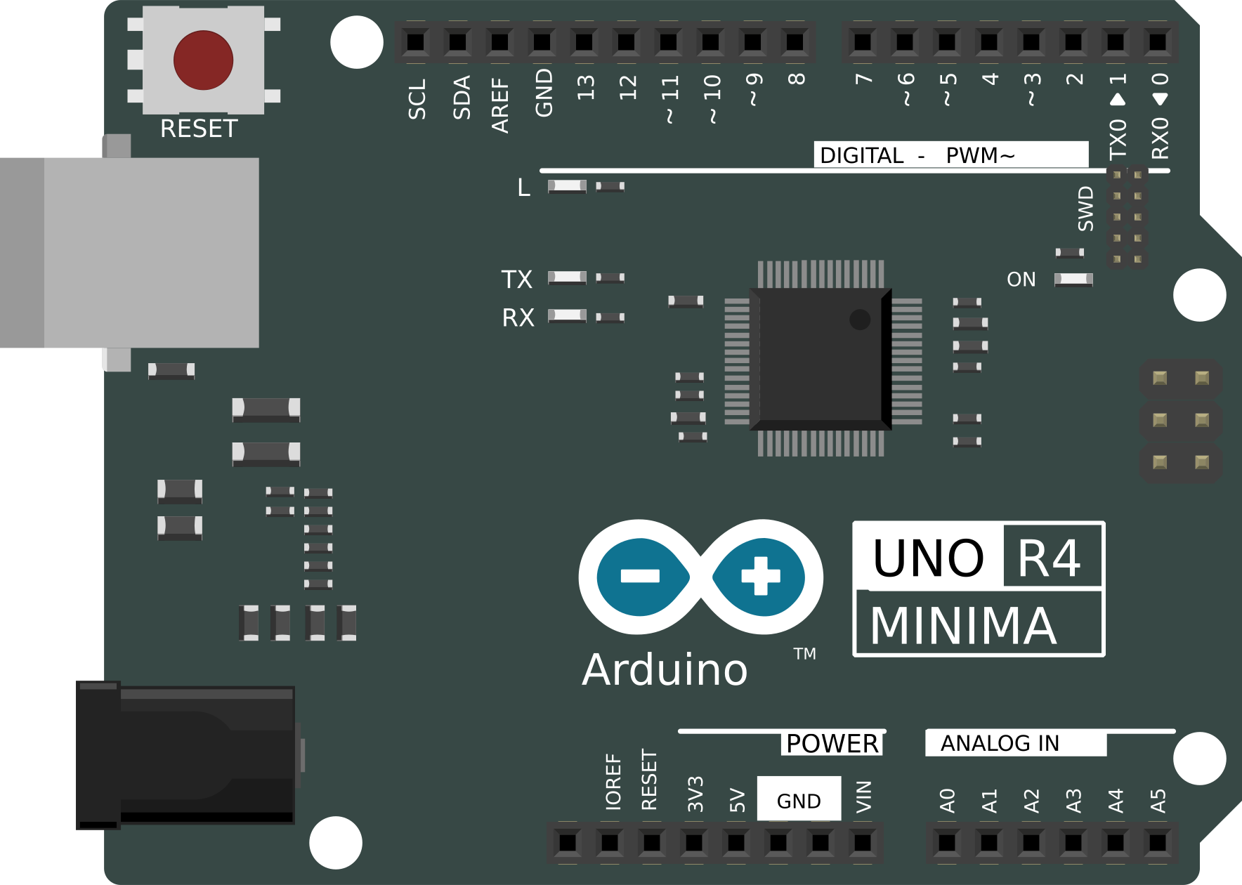
How to Use Arduino UNO R4 Minima: Examples, Pinouts, and Specs
Introduction
The R4 Minima is a compact resistor designed for applications where space is a critical factor. It offers precise resistance values, excellent stability, and reliability, making it an ideal choice for modern electronic circuits. Its small form factor allows it to be used in densely packed PCBs, portable devices, and other miniaturized systems. The R4 Minima is suitable for both analog and digital circuits, ensuring consistent performance across a wide range of operating conditions.
Explore Projects Built with Arduino UNO R4 Minima
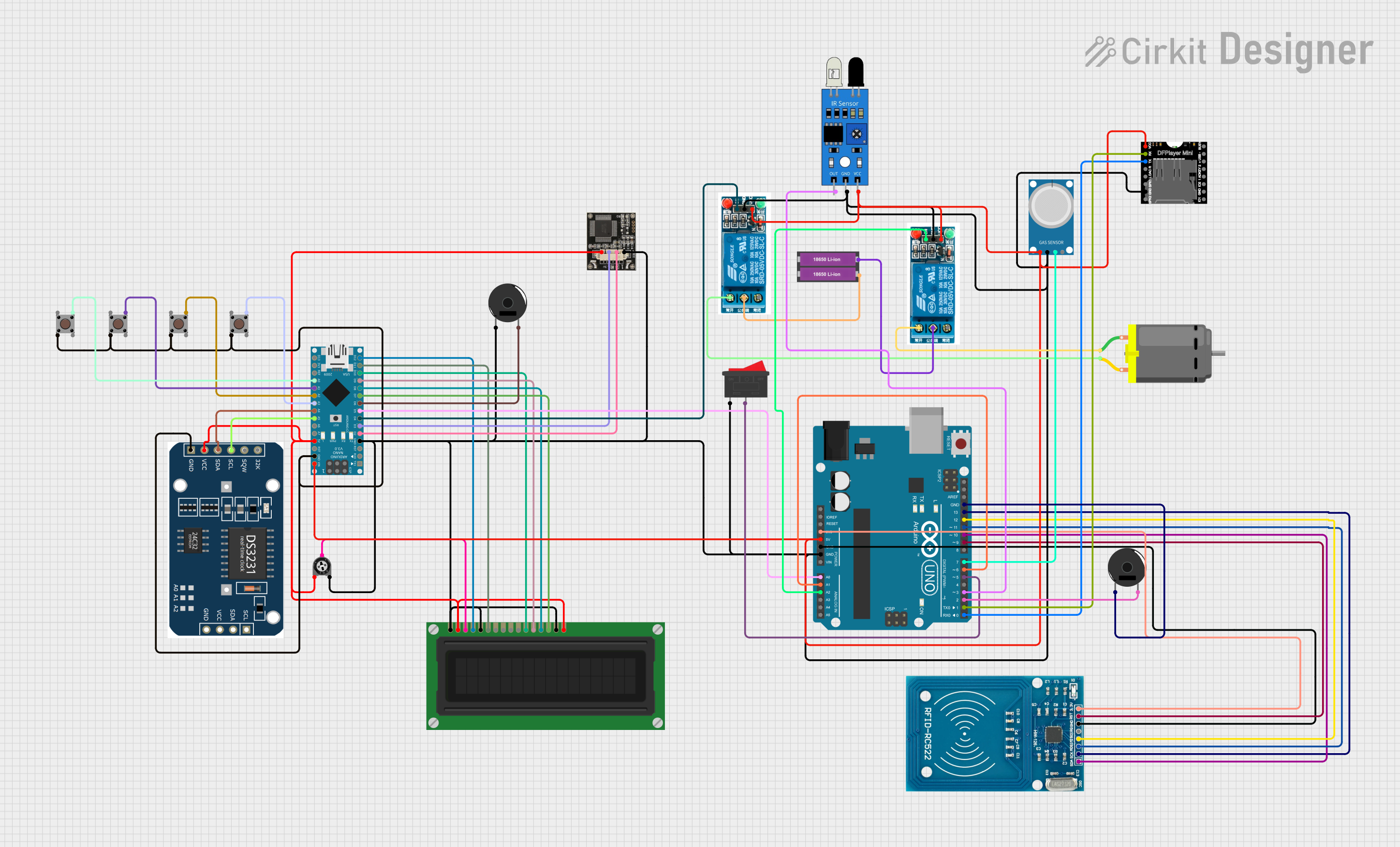
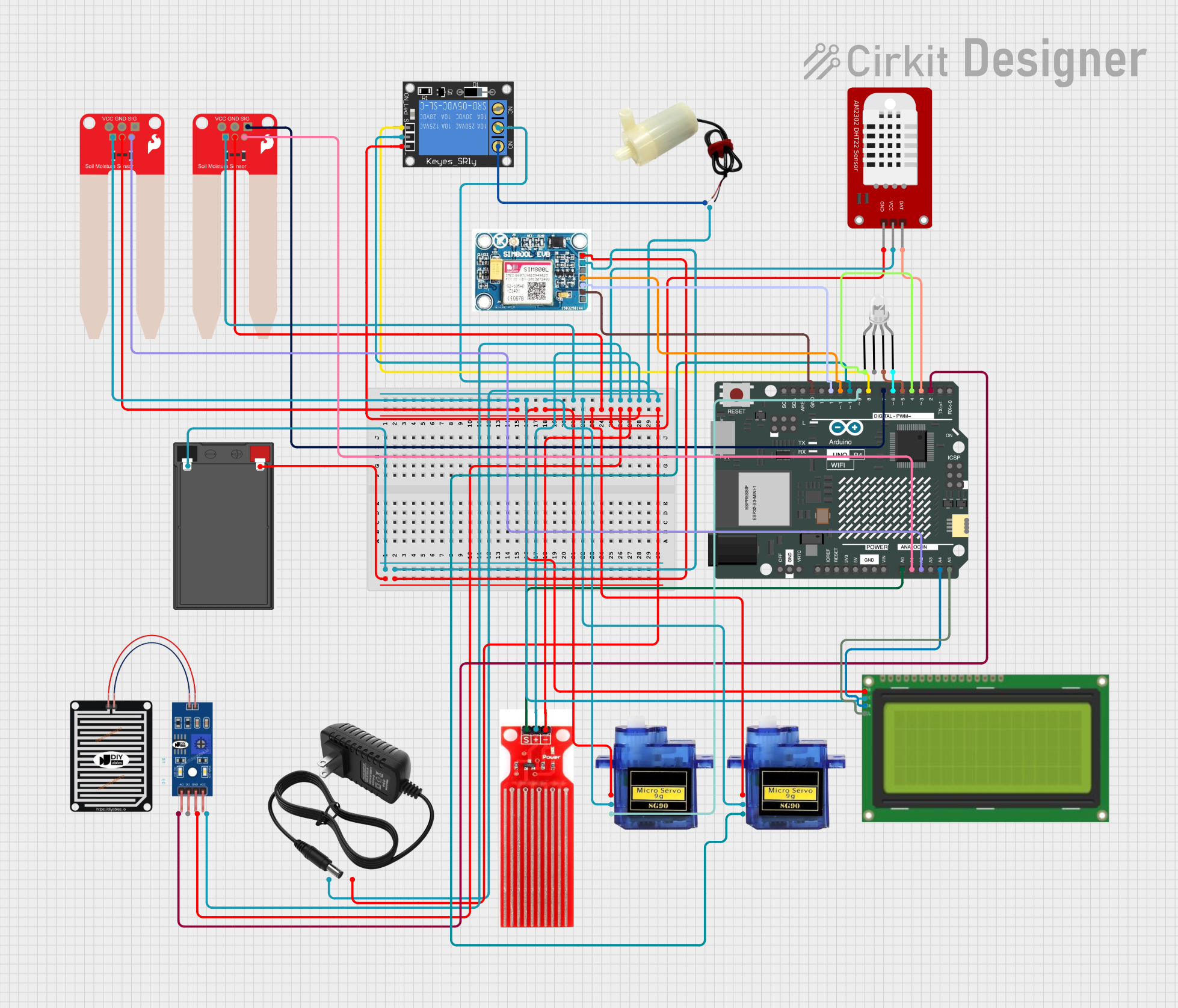
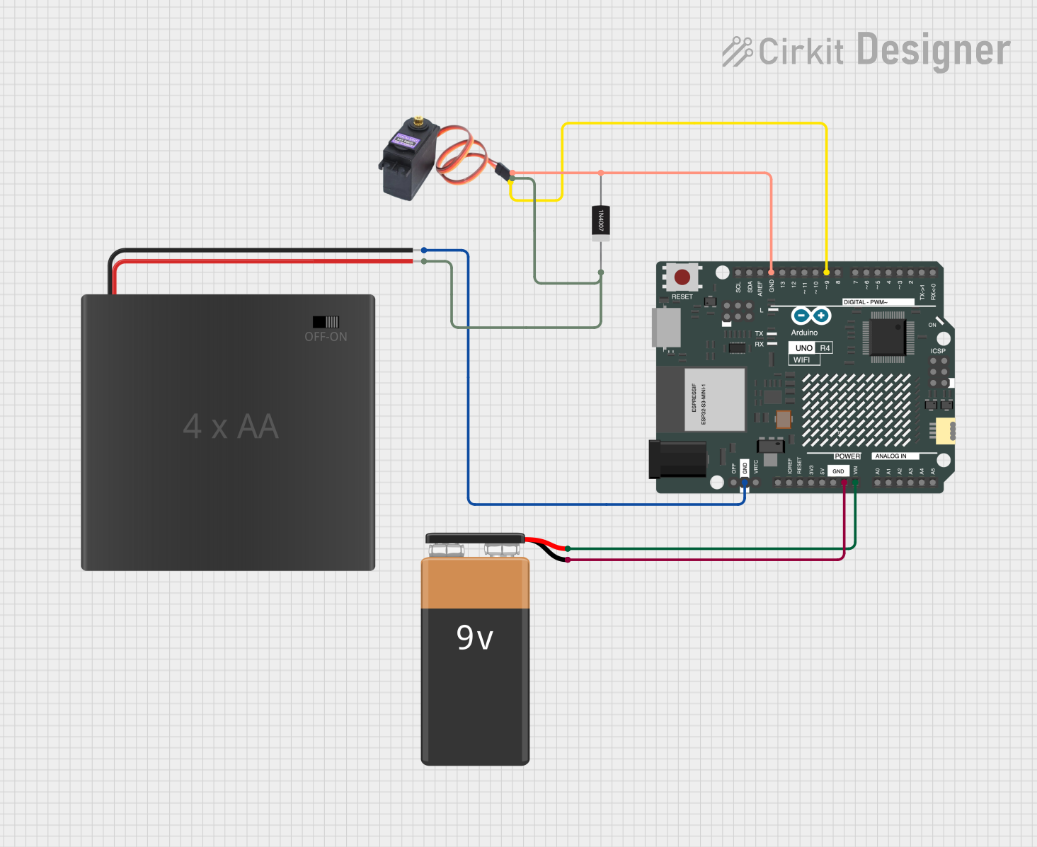
Explore Projects Built with Arduino UNO R4 Minima
Common Applications
- Portable electronic devices (e.g., smartphones, wearables)
- High-density printed circuit boards (PCBs)
- Precision measurement circuits
- Signal conditioning and filtering
- Power management systems
Technical Specifications
The R4 Minima is available in various resistance values and tolerances to suit different design requirements. Below are the key technical details:
General Specifications
| Parameter | Value |
|---|---|
| Resistance Range | 1 Ω to 1 MΩ |
| Tolerance | ±0.1%, ±0.5%, ±1% |
| Power Rating | 0.125 W (1/8 W) |
| Temperature Coefficient | ±50 ppm/°C |
| Operating Temperature | -55°C to +155°C |
| Package Type | Surface Mount (SMD) or Through-Hole |
Pin Configuration and Descriptions
The R4 Minima is a two-terminal passive component. Below is the pin configuration:
| Pin Number | Description |
|---|---|
| 1 | Resistor Terminal 1 (Input) |
| 2 | Resistor Terminal 2 (Output) |
Usage Instructions
How to Use the R4 Minima in a Circuit
- Determine the Required Resistance Value: Select the appropriate resistance value based on your circuit's requirements. Use Ohm's Law (V = IR) to calculate the necessary resistance.
- Choose the Correct Package: Depending on your PCB design, select either the SMD or through-hole version of the R4 Minima.
- Soldering Guidelines:
- For SMD: Use a reflow soldering process with a compatible solder paste.
- For Through-Hole: Insert the leads into the PCB holes and solder them securely.
- Placement: Ensure the resistor is placed in the correct orientation. While resistors are non-polarized, proper alignment ensures neat assembly.
- Verify Connections: Use a multimeter to confirm the resistance value and check for proper connections.
Important Considerations
- Power Dissipation: Ensure the resistor's power rating (0.125 W) is not exceeded to avoid overheating or damage.
- Temperature Effects: Consider the temperature coefficient (±50 ppm/°C) for applications requiring high precision.
- Parasitic Effects: In high-frequency circuits, account for parasitic inductance and capacitance, which may affect performance.
Example: Using R4 Minima with an Arduino UNO
The R4 Minima can be used in a voltage divider circuit to interface sensors with the Arduino UNO. Below is an example:
Circuit Description
- A 10 kΩ R4 Minima resistor is used in series with a photoresistor to create a voltage divider.
- The output voltage is read by the Arduino's analog input pin.
Code Example
// Define the analog pin connected to the voltage divider
const int sensorPin = A0;

void setup() {
  Serial.begin(9600); // Initialize serial communication at 9600 baud
}

void loop() {
  int sensorValue = analogRead(sensorPin); // Read the analog value
  float voltage = sensorValue * (5.0 / 1023.0); // Convert to voltage
  Serial.print("Sensor Voltage: ");
  Serial.println(voltage); // Print the voltage to the Serial Monitor
  delay(500); // Wait for 500 ms before the next reading
}
Troubleshooting and FAQs
Common Issues
Incorrect Resistance Value:
- Cause: Misreading the resistor's value or selecting the wrong part.
- Solution: Double-check the resistance value using a multimeter or refer to the resistor's datasheet.
Overheating:
- Cause: Exceeding the resistor's power rating.
- Solution: Ensure the power dissipation does not exceed 0.125 W. Use a resistor with a higher power rating if necessary.
Poor Solder Joints:
- Cause: Inadequate soldering during assembly.
- Solution: Inspect and re-solder the connections to ensure proper contact.
Unstable Readings in Circuits:
- Cause: Temperature variations or parasitic effects in high-frequency circuits.
- Solution: Use resistors with a low temperature coefficient and minimize parasitic effects by proper PCB design.
FAQs
Q1: Can the R4 Minima be used in high-power applications?
A1: No, the R4 Minima is rated for 0.125 W. For high-power applications, use resistors with higher power ratings.
Q2: Is the R4 Minima polarized?
A2: No, resistors are non-polarized components and can be connected in either orientation.
Q3: How do I calculate the power dissipation of the R4 Minima?
A3: Use the formula ( P = I^2 \times R ) or ( P = V^2 / R ), where ( P ) is power, ( I ) is current, and ( R ) is resistance.
Q4: Can I use the R4 Minima in RF circuits?
A4: Yes, but consider the parasitic inductance and capacitance, which may affect performance at high frequencies.