How to Use L86: Examples, Pinouts, and Specs
Introduction
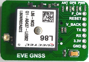
The L86 is an inductor manufactured by Quectel, designed to store energy in a magnetic field when electrical current flows through it. Inductors like the L86 are essential components in electronic circuits, particularly for filtering and energy storage applications. The L86 is commonly used in power supply circuits, signal filtering, and electromagnetic interference (EMI) suppression.
Explore Projects Built with L86
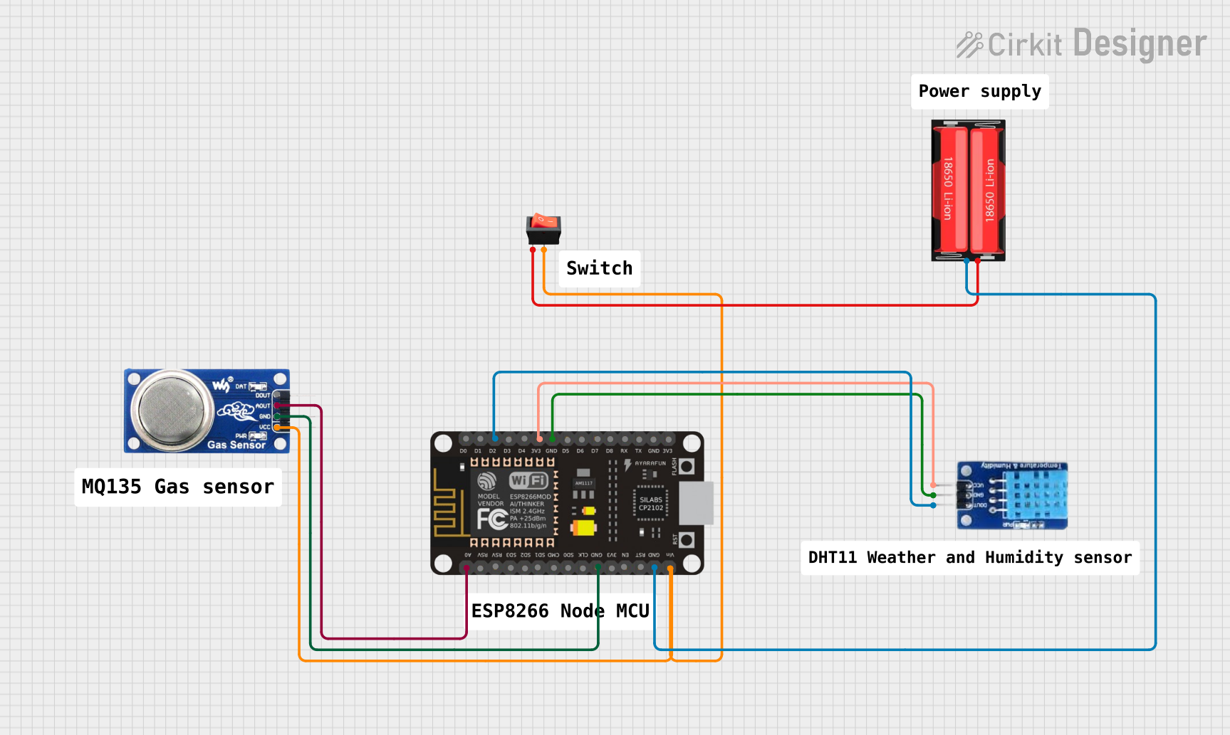

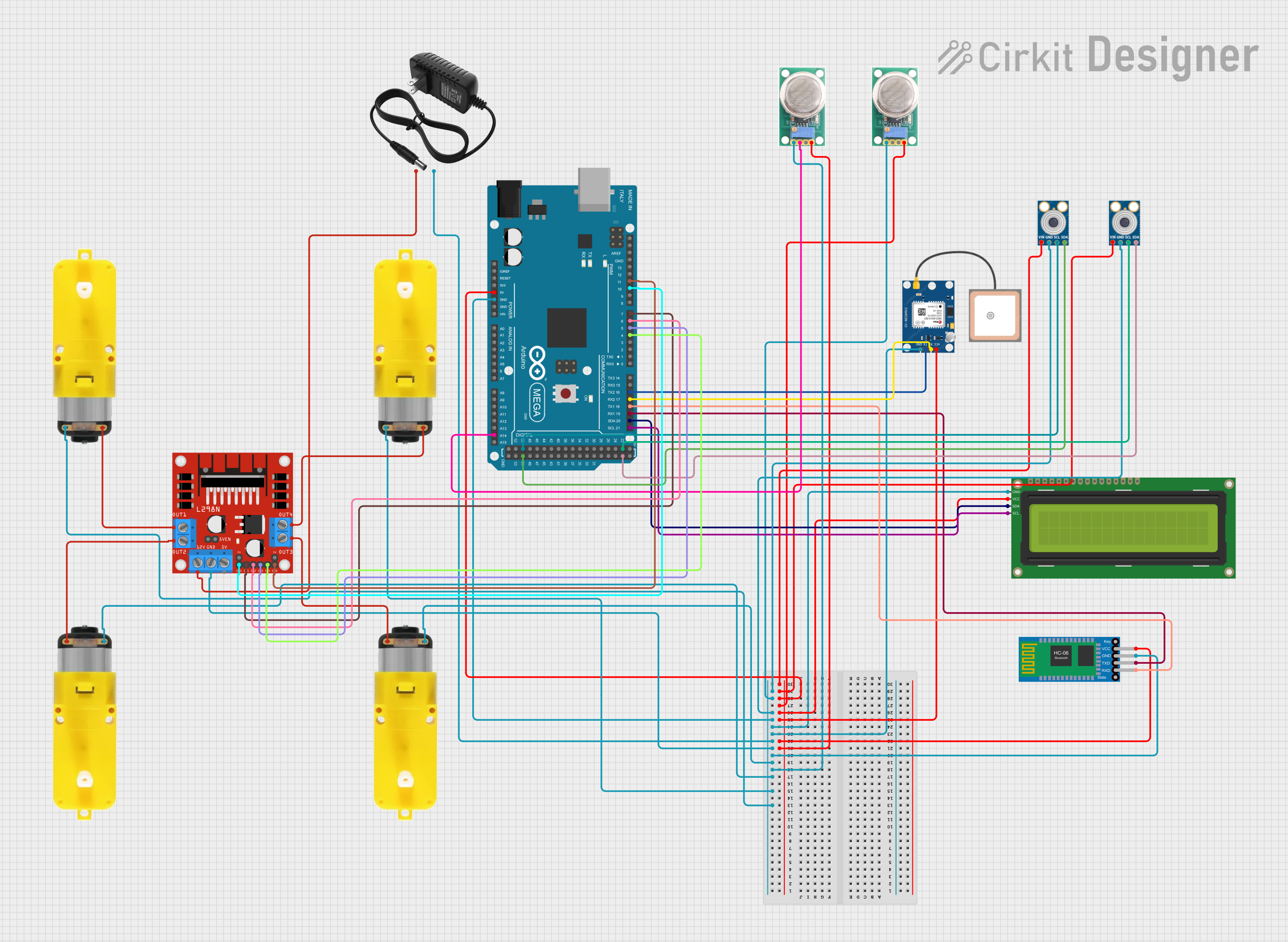
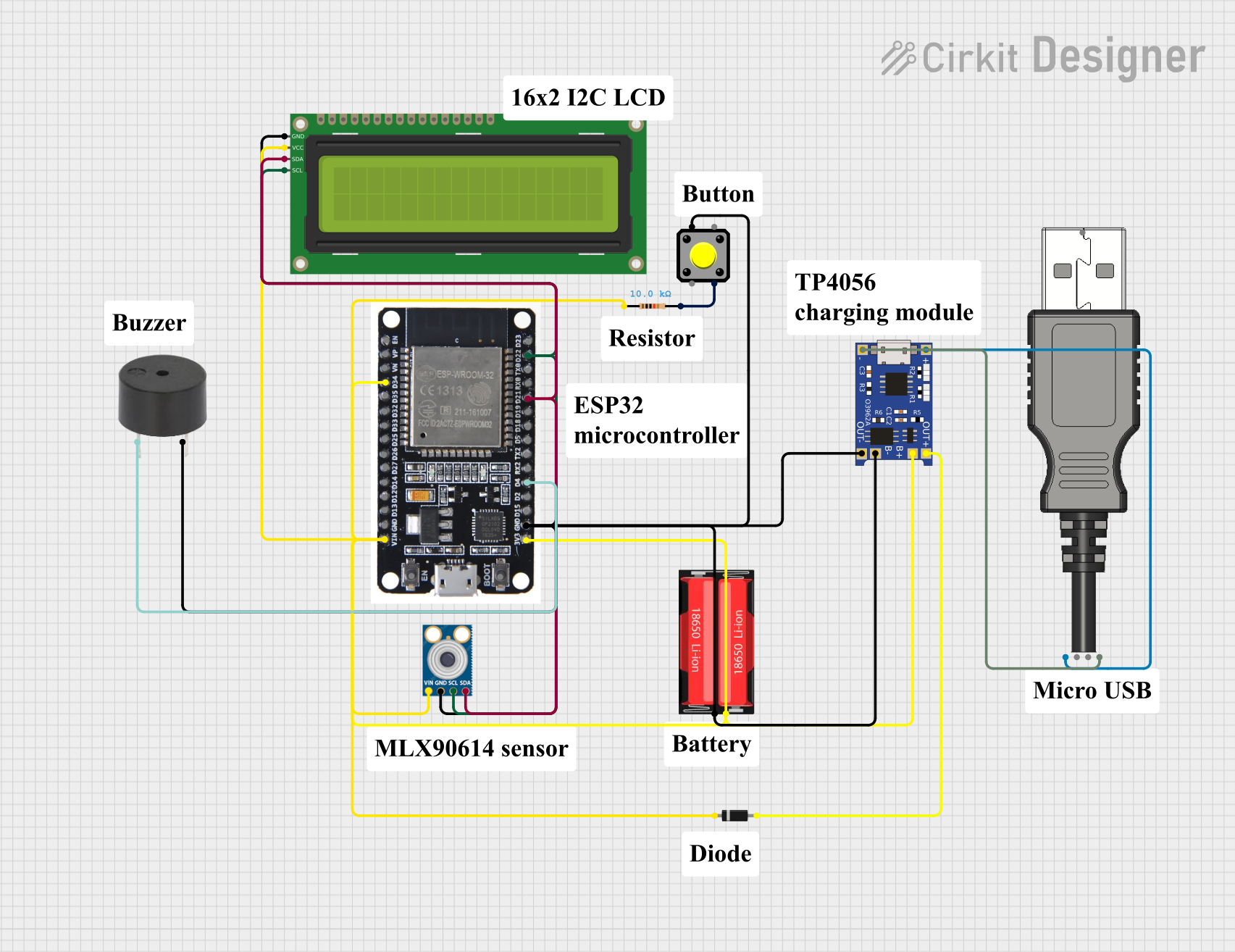
Explore Projects Built with L86
Common Applications:
- Power supply circuits for energy storage and voltage regulation
- Low-pass and high-pass filters in signal processing
- EMI suppression in sensitive electronic devices
- DC-DC converters and switching regulators
Technical Specifications
The L86 inductor is designed to meet the needs of modern electronic circuits with high efficiency and reliability. Below are the key technical specifications:
| Parameter | Value |
|---|---|
| Inductance | 10 µH (typical) |
| Tolerance | ±10% |
| Rated Current | 2.5 A |
| Saturation Current | 3.0 A |
| DC Resistance (DCR) | 0.05 Ω (max) |
| Operating Temperature | -40°C to +125°C |
| Core Material | Ferrite |
| Package Type | SMD (Surface-Mount Device) |
Pin Configuration and Descriptions
The L86 is a two-terminal component with no polarity, making it easy to integrate into circuits. Below is the pin configuration:
| Pin | Description |
|---|---|
| Pin 1 | Input/Output terminal |
| Pin 2 | Input/Output terminal |
Note: Since the L86 is non-polarized, either pin can serve as the input or output.
Usage Instructions
The L86 inductor is straightforward to use in electronic circuits. Follow the steps and guidelines below to ensure optimal performance:
How to Use the L86 in a Circuit:
Determine the Required Inductance:
- Calculate the required inductance value for your application using circuit design equations.
- Ensure the L86's 10 µH inductance meets your design requirements.
Check Current Ratings:
- Verify that the circuit's current does not exceed the L86's rated current of 2.5 A.
- If the current exceeds the saturation current (3.0 A), the inductor may lose its inductive properties.
Place the Inductor in the Circuit:
- Solder the L86 onto the PCB using its SMD package.
- Connect the inductor in series for filtering or energy storage applications.
Use in Filtering Applications:
- For low-pass filters, place the L86 in series with the signal path.
- For high-pass filters, combine the L86 with a capacitor in a parallel configuration.
Verify Connections:
- Double-check the solder joints and connections to ensure proper electrical contact.
Important Considerations:
- Avoid Overheating: Ensure the operating temperature remains within the -40°C to +125°C range.
- Minimize Parasitics: Place the inductor close to other components to reduce parasitic inductance and resistance.
- Use Proper Decoupling: When used in power supply circuits, pair the L86 with capacitors for effective decoupling.
Example: Using the L86 with an Arduino UNO
The L86 can be used in conjunction with an Arduino UNO for filtering noise in power supply lines. Below is an example circuit and code to demonstrate its use:
Circuit Description:
- The L86 is placed in series with the 5V power supply line to filter out high-frequency noise.
- A 10 µF capacitor is connected in parallel to the power supply for additional filtering.
Arduino Code:
// Example code to demonstrate a simple Arduino setup
// This code toggles an LED while the L86 inductor filters noise
// in the power supply line.

const int ledPin = 13; // Pin connected to the onboard LED

void setup() {
  pinMode(ledPin, OUTPUT); // Set the LED pin as an output
}

void loop() {
  digitalWrite(ledPin, HIGH); // Turn the LED on
  delay(1000);                // Wait for 1 second
  digitalWrite(ledPin, LOW);  // Turn the LED off
  delay(1000);                // Wait for 1 second
}
Note: The L86 is not directly controlled by the Arduino but plays a critical role in ensuring a stable power supply for the microcontroller.
Troubleshooting and FAQs
Common Issues:
Inductor Overheating:
- Cause: Excessive current or high ambient temperature.
- Solution: Ensure the current does not exceed the rated or saturation current. Improve ventilation or use a heat sink if necessary.
Circuit Noise Not Reduced:
- Cause: Incorrect placement or insufficient filtering.
- Solution: Verify the inductor is placed correctly in the circuit. Pair the L86 with appropriate capacitors for better filtering.
Inductor Fails to Function:
- Cause: Damaged component or poor soldering.
- Solution: Inspect the inductor for physical damage. Re-solder the connections if needed.
FAQs:
Q: Can the L86 be used in high-frequency circuits?
A: Yes, the L86 is suitable for high-frequency applications, but ensure the core material and inductance value meet the circuit's requirements.Q: Is the L86 polarized?
A: No, the L86 is a non-polarized component, so either pin can be used as input or output.Q: How do I calculate the required inductance for my circuit?
A: Use the formula ( L = \frac{V}{\Delta I \cdot f} ), where ( V ) is voltage, ( \Delta I ) is the ripple current, and ( f ) is the switching frequency.
By following this documentation, users can effectively integrate the L86 inductor into their electronic designs for reliable and efficient performance.