
How to Use MOV-14D471K: Examples, Pinouts, and Specs
 Design with MOV-14D471K in Cirkit Designer
Introduction
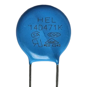
The MOV-14D471K is a Metal Oxide Varistor (MOV) designed for voltage clamping and surge protection in electronic circuits. Manufactured by Arduino under the part ID "Nano," this component is rated for 470V and is capable of absorbing high transient voltages, making it an essential component for protecting sensitive electronic devices from voltage spikes and surges.
Explore Projects Built with MOV-14D471K
 Open Project in Cirkit Designer
 Open Project in Cirkit Designer
 Open Project in Cirkit Designer
 Open Project in Cirkit Designer
Explore Projects Built with MOV-14D471K
Open Project in Cirkit DesignerOpen Project in Cirkit DesignerOpen Project in Cirkit DesignerOpen Project in Cirkit DesignerCommon Applications and Use Cases
- Surge protection in power supplies and electronic circuits
- Voltage clamping in industrial and consumer electronics
- Protection of microcontrollers, sensors, and other sensitive components
- Used in AC and DC circuits for transient voltage suppression
Technical Specifications
The MOV-14D471K is a robust and reliable component with the following key specifications:
| Parameter | Value |
|---|---|
| Manufacturer | Arduino |
| Part ID | Nano |
| Varistor Voltage (V1mA) | 470V |
| Maximum Clamping Voltage | 775V |
| Maximum Energy Absorption | 70 Joules |
| Peak Current (8/20 µs) | 4,500A |
| Operating Voltage Range | 380V AC / 615V DC |
| Response Time | < 25 ns |
| Operating Temperature | -40°C to +85°C |
| Diameter | 14 mm |
Pin Configuration and Descriptions
The MOV-14D471K is a two-terminal device with no polarity, meaning it can be connected in either direction. Below is the pin configuration:
| Pin | Description |
|---|---|
| Pin 1 | Connects to the input voltage line |
| Pin 2 | Connects to the ground or return line |
Usage Instructions
How to Use the MOV-14D471K in a Circuit
- Placement in Circuit: The MOV-14D471K should be connected across the power supply lines (line and neutral in AC circuits or positive and ground in DC circuits). It is typically placed in parallel with the load to protect it from voltage surges.
- Connection: Since the MOV is non-polarized, either terminal can be connected to the input voltage line or ground.
- Fuse Protection: For enhanced safety, it is recommended to use a fuse in series with the MOV. This prevents damage to the circuit in case of prolonged overvoltage conditions.
- PCB Mounting: The MOV-14D471K is designed for through-hole mounting. Ensure proper spacing between the leads to avoid short circuits.
Important Considerations and Best Practices
- Voltage Rating: Ensure the operating voltage of the circuit does not exceed the MOV's maximum operating voltage (380V AC or 615V DC).
- Thermal Management: Avoid placing the MOV near heat-sensitive components, as it may generate heat during operation.
- Transient Protection: Use the MOV in conjunction with other protection devices like fuses or thermal cutoffs for comprehensive protection.
- Testing: Regularly test the MOV for degradation, as repeated surges can reduce its effectiveness over time.
Example: Using MOV-14D471K with Arduino UNO
The MOV-14D471K can be used to protect an Arduino UNO from voltage surges. Below is an example circuit and code to demonstrate its usage:
Circuit Description
- Connect the MOV-14D471K across the 5V and GND pins of the Arduino UNO to protect it from transient voltage spikes.
- Use a 1A fuse in series with the 5V line for additional protection.
Arduino Code Example
// Example code to demonstrate Arduino UNO functionality
// This code reads an analog input and outputs the value to the serial monitor.

const int analogPin = A0; // Analog pin connected to a sensor
int sensorValue = 0;      // Variable to store the sensor value

void setup() {
  Serial.begin(9600); // Initialize serial communication at 9600 baud
}

void loop() {
  sensorValue = analogRead(analogPin); // Read the analog input
  Serial.println(sensorValue);        // Print the value to the serial monitor
  delay(500);                         // Wait for 500ms before the next reading
}
Note: The MOV does not directly interact with the Arduino code but provides hardware-level protection for the board.
Troubleshooting and FAQs
Common Issues Users Might Face
MOV Overheating:
- Cause: Prolonged exposure to overvoltage or repeated surges.
- Solution: Check the circuit's operating voltage and ensure it is within the MOV's rated range. Replace the MOV if it shows signs of damage.
Circuit Not Protected from Surges:
- Cause: Incorrect placement of the MOV in the circuit.
- Solution: Verify that the MOV is connected across the power supply lines and not in series with the load.
MOV Fails to Clamp Voltage:
- Cause: Degraded MOV due to repeated surges.
- Solution: Replace the MOV and consider using additional protection devices like fuses.
FAQs
Q1: Can the MOV-14D471K be used in DC circuits?
A1: Yes, the MOV-14D471K can be used in DC circuits with a maximum operating voltage of 615V DC.
Q2: How do I know if the MOV is damaged?
A2: A damaged MOV may show physical signs like discoloration, cracking, or bulging. It may also fail to clamp voltage effectively, leading to unprotected circuits.
Q3: Can I use multiple MOVs in parallel for higher surge protection?
A3: Yes, multiple MOVs can be used in parallel to share the surge current. However, ensure they have identical specifications for balanced operation.
Q4: What happens if the MOV is exposed to continuous overvoltage?
A4: Continuous overvoltage can cause the MOV to overheat and fail. Always use a fuse in series with the MOV to prevent such scenarios.
By following this documentation, users can effectively integrate the MOV-14D471K into their circuits for reliable surge protection.