
How to Use SC16IS750: Examples, Pinouts, and Specs
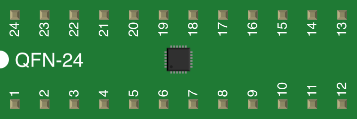
 Design with SC16IS750 in Cirkit Designer
Introduction
The SC16IS750, manufactured by NXP Semiconductors, is a high-performance I2C/SPI to UART bridge. This versatile component enables seamless serial communication between microcontrollers and other devices. It features a built-in 64-byte FIFO buffer for both transmit and receive operations, supports a wide range of baud rates, and can be configured for either I2C or SPI communication protocols.
Explore Projects Built with SC16IS750
 Open Project in Cirkit Designer
 Open Project in Cirkit Designer
 Open Project in Cirkit Designer
 Open Project in Cirkit Designer
Explore Projects Built with SC16IS750
Open Project in Cirkit DesignerOpen Project in Cirkit DesignerOpen Project in Cirkit DesignerOpen Project in Cirkit DesignerCommon Applications and Use Cases
- Serial communication with microcontrollers in embedded systems
- Expanding UART interfaces in systems with limited UART ports
- Communication with sensors, modems, or other UART-based peripherals
- Industrial automation and IoT devices requiring reliable data transmission
- Debugging and monitoring serial data streams
Technical Specifications
The SC16IS750 is designed to provide robust and flexible serial communication. Below are its key technical details:
Key Technical Details
| Parameter | Value |
|---|---|
| Supply Voltage (VDD) | 2.5 V to 3.3 V |
| I/O Voltage Range | 1.8 V to 3.3 V |
| Communication Protocols | I2C, SPI |
| UART Baud Rate | Up to 5 Mbps |
| FIFO Buffer Size | 64 bytes (TX and RX each) |
| Operating Temperature | -40°C to +85°C |
| Package Type | HVQFN24, TSSOP28 |
Pin Configuration and Descriptions
The SC16IS750 is available in multiple package types. Below is the pin configuration for the TSSOP28 package:
| Pin Number | Pin Name | Description |
|---|---|---|
| 1 | A0 | I2C address selection or SPI chip select |
| 2 | A1 | I2C address selection |
| 3 | A2 | I2C address selection |
| 4 | RESET | Active-low reset input |
| 5 | XTAL1 | Crystal oscillator input |
| 6 | XTAL2 | Crystal oscillator output |
| 7 | VSS | Ground |
| 8 | TXD | UART transmit data |
| 9 | RXD | UART receive data |
| 10 | RTS | UART request to send |
| 11 | CTS | UART clear to send |
| 12 | GPIO0 | General-purpose I/O |
| 13 | GPIO1 | General-purpose I/O |
| 14 | GPIO2 | General-purpose I/O |
| 15 | GPIO3 | General-purpose I/O |
| 16 | VDD | Power supply |
| 17 | SCL/SCLK | I2C clock or SPI clock |
| 18 | SDA/MOSI | I2C data or SPI master out/slave in |
| 19 | IRQ | Interrupt request output |
| 20 | NC | No connection |
| 21 | NC | No connection |
| 22 | NC | No connection |
| 23 | NC | No connection |
| 24 | NC | No connection |
| 25 | NC | No connection |
| 26 | NC | No connection |
| 27 | NC | No connection |
| 28 | NC | No connection |
Usage Instructions
How to Use the SC16IS750 in a Circuit
- Power Supply: Connect the VDD pin to a 2.5 V to 3.3 V power source and the VSS pin to ground.
- Communication Protocol Selection:
- For I2C: Connect the SCL and SDA pins to the I2C bus of the microcontroller.
- For SPI: Connect the SCLK, MOSI, and MISO pins to the SPI bus of the microcontroller.
- UART Interface: Connect the TXD and RXD pins to the UART device for serial communication.
- Address Configuration: Use the A0, A1, and A2 pins to set the I2C address or SPI chip select.
- Interrupt Handling: Connect the IRQ pin to the microcontroller to handle interrupts.
- Crystal Oscillator: Connect a crystal oscillator to the XTAL1 and XTAL2 pins for clock generation.
Important Considerations and Best Practices
- Pull-Up Resistors: For I2C communication, ensure pull-up resistors are connected to the SCL and SDA lines.
- Baud Rate Configuration: Configure the baud rate registers to match the UART device's baud rate.
- FIFO Management: Use the FIFO buffer to handle high-speed data transmission efficiently.
- Reset: Use the RESET pin to initialize the device during power-up or after a fault condition.
- Voltage Levels: Ensure that the I/O voltage levels are compatible with the microcontroller.
Example: Using SC16IS750 with Arduino UNO (I2C Mode)
Below is an example Arduino sketch to communicate with the SC16IS750 over I2C:
#include <Wire.h> // Include the Wire library for I2C communication

#define SC16IS750_ADDR 0x48 // Replace with the actual I2C address of the SC16IS750

void setup() {
  Wire.begin(); // Initialize I2C communication
  Serial.begin(9600); // Initialize serial communication for debugging

  // Configure SC16IS750 (example: set baud rate to 9600)
  Wire.beginTransmission(SC16IS750_ADDR);
  Wire.write(0x03); // LCR register address
  Wire.write(0x80); // Enable access to baud rate registers
  Wire.endTransmission();

  Wire.beginTransmission(SC16IS750_ADDR);
  Wire.write(0x00); // DLL register address
  Wire.write(0x60); // Set baud rate divisor (9600 baud)
  Wire.endTransmission();

  Wire.beginTransmission(SC16IS750_ADDR);
  Wire.write(0x01); // DLM register address
  Wire.write(0x00); // Set baud rate divisor (9600 baud)
  Wire.endTransmission();

  Wire.beginTransmission(SC16IS750_ADDR);
  Wire.write(0x03); // LCR register address
  Wire.write(0x03); // 8 data bits, no parity, 1 stop bit
  Wire.endTransmission();

  Serial.println("SC16IS750 configured successfully!");
}

void loop() {
  // Example: Send data to SC16IS750
  Wire.beginTransmission(SC16IS750_ADDR);
  Wire.write(0x00); // THR register address
  Wire.write("Hello, SC16IS750!"); // Send a string
  Wire.endTransmission();

  delay(1000); // Wait for 1 second
}
Troubleshooting and FAQs
Common Issues and Solutions
No Communication with the SC16IS750:
- Verify the I2C or SPI connections and ensure proper pull-up resistors are used for I2C.
- Check the I2C address or SPI chip select configuration.
- Ensure the power supply voltage is within the specified range.
Data Loss or Corruption:
- Ensure the baud rate is correctly configured on both the SC16IS750 and the UART device.
- Use the FIFO buffer to handle high-speed data transmission.
Interrupts Not Triggering:
- Verify the IRQ pin connection to the microcontroller.
- Check the interrupt enable registers in the SC16IS750.
FAQs
Q: Can the SC16IS750 operate in both I2C and SPI modes simultaneously?
A: No, the SC16IS750 can operate in either I2C or SPI mode, but not both simultaneously. The mode is determined by the hardware connections.
Q: What is the maximum UART baud rate supported?
A: The SC16IS750 supports UART baud rates up to 5 Mbps.
Q: How do I reset the SC16IS750?
A: Use the RESET pin to perform a hardware reset or write to the appropriate register for a software reset.
Q: Can I use the GPIO pins for custom functions?
A: Yes, the GPIO pins can be configured as general-purpose inputs or outputs.