How to Use 12V DC FAN: Examples, Pinouts, and Specs
12V DC Fan Documentation
Manufacturer: AC
Part ID: Fan
1. Introduction
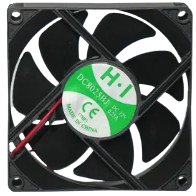
The 12V DC Fan is a compact and efficient cooling solution designed to operate on a 12-volt direct current (DC) power supply. It is widely used in various applications to dissipate heat and maintain optimal operating temperatures for electronic devices and components. The fan is lightweight, durable, and energy-efficient, making it an essential component in thermal management systems.
Common Applications:
- Cooling computer processors, power supplies, and other electronic components.
- Ventilation in enclosures, cabinets, and small appliances.
- Heat dissipation in 3D printers, robotics, and DIY electronics projects.
- Automotive applications for auxiliary cooling.
2. Technical Specifications
The following table outlines the key technical details of the 12V DC Fan:
| Parameter | Value | Description |
|---|---|---|
| Operating Voltage | 12V DC | Nominal voltage required for operation. |
| Operating Current | 0.15A (typical) | Typical current consumption during operation. |
| Power Consumption | 1.8W | Power required for operation. |
| Fan Speed | 3000 RPM (±10%) | Rotational speed of the fan blades. |
| Airflow | 40 CFM (Cubic Feet per Minute) | Volume of air moved by the fan. |
| Noise Level | 25 dBA | Noise generated during operation. |
| Dimensions | 80mm x 80mm x 25mm | Standard size for compatibility. |
| Bearing Type | Sleeve or Ball Bearing | Determines durability and noise level. |
| Connector Type | 2-pin or 3-pin | For power and optional speed monitoring. |
Pin Configuration
| Pin | Name | Description |
|---|---|---|
| 1 | VCC (+12V) | Positive power supply input (12V DC). |
| 2 | GND | Ground connection for the power supply. |
| 3* | Tachometer (T) | Optional pin for speed monitoring (available only in 3-pin fans). |
*Note: The tachometer pin is only present in 3-pin fans and provides a pulse signal for RPM monitoring.
3. Usage Instructions
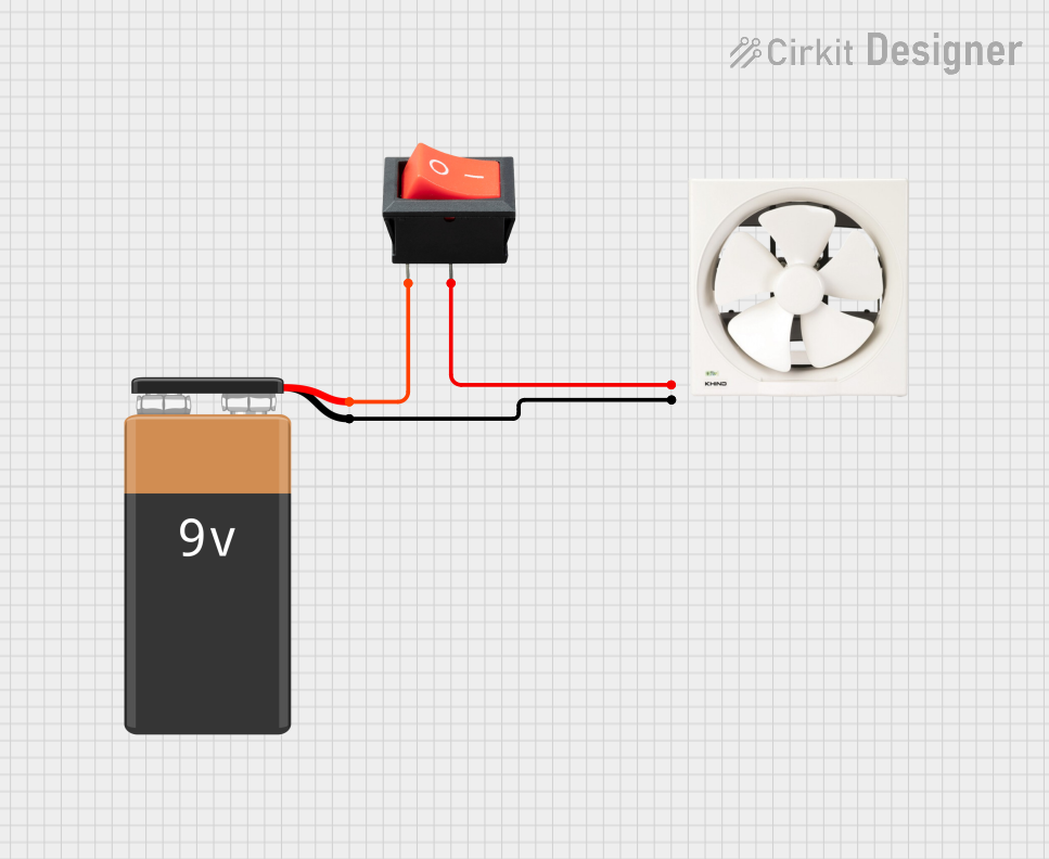
Connecting the 12V DC Fan to a Circuit
Power Supply:
- Connect the VCC (+12V) pin to a 12V DC power source.
- Connect the GND pin to the ground of the power source.
Optional Speed Monitoring (3-pin fans):
- If using a 3-pin fan, connect the Tachometer (T) pin to a microcontroller or monitoring circuit to measure the fan's speed.
Mounting:
- Secure the fan using screws or adhesive mounts to ensure proper airflow.
- Ensure the airflow direction aligns with the cooling requirements (check the arrow markings on the fan).
Important Considerations:
- Voltage Tolerance: Do not exceed the rated 12V DC input to avoid damaging the fan.
- Polarity: Ensure correct polarity when connecting the power supply. Reversing the polarity may damage the fan.
- Airflow Clearance: Maintain sufficient clearance around the fan for unobstructed airflow.
- Noise Reduction: Use rubber mounts or grommets to minimize vibration and noise.
4. Example: Controlling a 12V DC Fan with Arduino UNO
The following example demonstrates how to control the speed of a 12V DC fan using an Arduino UNO and a PWM signal. A transistor (e.g., NPN type like 2N2222) is used to drive the fan.
Circuit Diagram:
- Connect the VCC pin of the fan to a 12V power supply.
- Connect the GND pin of the fan to the collector of the NPN transistor.
- Connect the emitter of the transistor to the ground of the power supply.
- Connect a 10kΩ resistor between the base of the transistor and Arduino pin 9.
Code Example:
// Arduino code to control the speed of a 12V DC fan using PWM

// Define the PWM pin connected to the transistor base
const int fanPin = 9;

void setup() {
  // Set the fan pin as an output
  pinMode(fanPin, OUTPUT);
}

void loop() {
  // Gradually increase fan speed
  for (int speed = 0; speed <= 255; speed += 5) {
    analogWrite(fanPin, speed); // Write PWM signal to control fan speed
    delay(50); // Wait for 50ms
  }

  // Gradually decrease fan speed
  for (int speed = 255; speed >= 0; speed -= 5) {
    analogWrite(fanPin, speed); // Write PWM signal to control fan speed
    delay(50); // Wait for 50ms
  }
}
Notes:
- Use a flyback diode (e.g., 1N4007) across the fan terminals to protect the circuit from voltage spikes caused by the fan's inductive load.
- Ensure the transistor can handle the fan's current requirements.
5. Troubleshooting and FAQs
Common Issues and Solutions
| Issue | Possible Cause | Solution |
|---|---|---|
| Fan does not spin | Incorrect wiring or no power supply | Verify connections and ensure a 12V DC power supply is used. |
| Fan spins slowly or intermittently | Insufficient voltage or current | Check the power supply and ensure it meets the fan's specifications. |
| Excessive noise or vibration | Loose mounting or damaged bearings | Secure the fan properly or replace it if the bearings are worn out. |
| Fan speed not adjustable | Incorrect PWM signal or transistor failure | Verify the PWM signal and ensure the transistor is functioning correctly. |
FAQs
Q1: Can I use a 5V power supply for the 12V DC fan?
A1: No, the fan requires a 12V DC power supply for proper operation. Using a lower voltage may result in insufficient airflow or failure to start.
Q2: How do I determine the airflow direction of the fan?
A2: Most fans have arrow markings on the housing indicating the airflow direction and blade rotation.
Q3: Can I connect the fan directly to an Arduino?
A3: No, the Arduino cannot supply the required current for the fan. Use an external 12V power supply and a transistor to control the fan.
Q4: What is the purpose of the tachometer pin?
A4: The tachometer pin provides a pulse signal that can be used to monitor the fan's speed (RPM).
This documentation provides a comprehensive guide to understanding, using, and troubleshooting the 12V DC Fan. For further assistance, refer to the manufacturer's datasheet or contact technical support.
Explore Projects Built with 12V DC FAN


Explore Projects Built with 12V DC FAN