
How to Use STM32F411 BlackPill: Examples, Pinouts, and Specs
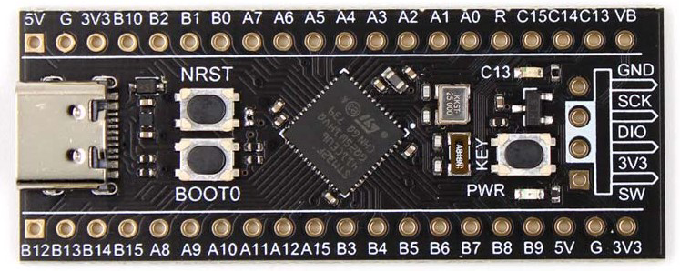
 Design with STM32F411 BlackPill in Cirkit Designer
Introduction
The STM32F411 BlackPill is a compact development board designed by STMicroelectronics, featuring the STM32F411 microcontroller. This microcontroller is part of the STM32 family, known for its high performance, low power consumption, and rich feature set. The BlackPill board is a popular choice for embedded systems and IoT projects due to its small form factor, versatile GPIO pins, and support for multiple communication protocols.
Explore Projects Built with STM32F411 BlackPill
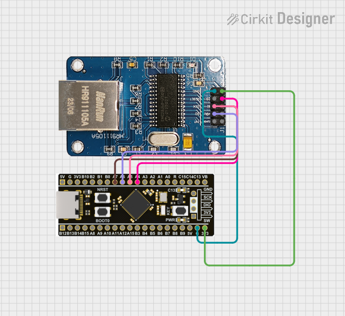 Open Project in Cirkit Designer
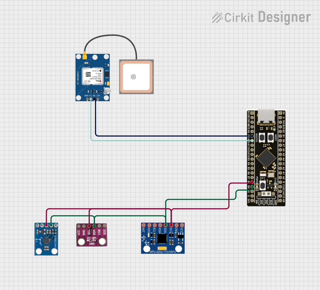 Open Project in Cirkit Designer
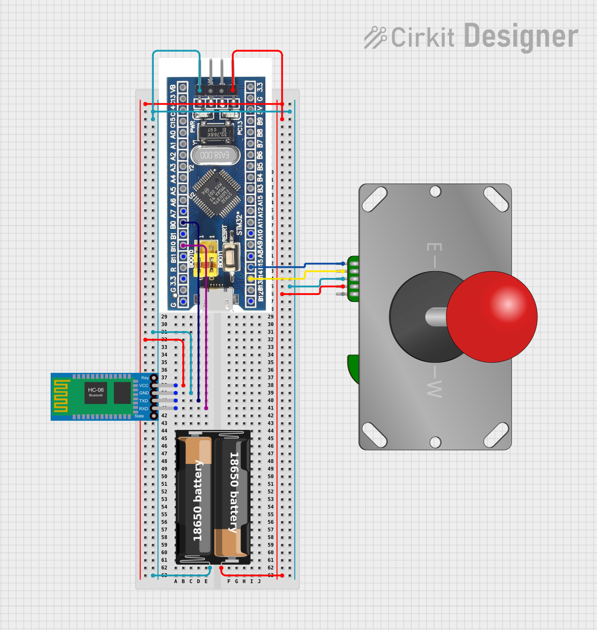 Open Project in Cirkit Designer
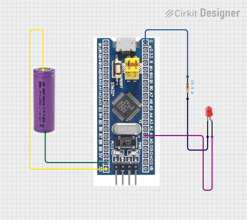 Open Project in Cirkit Designer
Explore Projects Built with STM32F411 BlackPill
Open Project in Cirkit DesignerOpen Project in Cirkit DesignerOpen Project in Cirkit DesignerOpen Project in Cirkit DesignerCommon Applications and Use Cases
- Prototyping embedded systems
- IoT devices and smart home applications
- Robotics and motor control
- Data acquisition and signal processing
- Educational projects and learning ARM Cortex-M4 architecture
Technical Specifications
The STM32F411 BlackPill is built around the STM32F411CEU6 microcontroller, which is based on the ARM Cortex-M4 core. Below are the key technical details:
Microcontroller Specifications
| Parameter | Value |
|---|---|
| Microcontroller | STM32F411CEU6 |
| Core | ARM Cortex-M4 with FPU |
| Operating Frequency | Up to 100 MHz |
| Flash Memory | 512 KB |
| SRAM | 128 KB |
| GPIO Pins | 37 (multipurpose, including ADC, PWM, etc.) |
| Communication Interfaces | I2C, SPI, UART, CAN, USB OTG, I2S |
| ADC Resolution | 12-bit, up to 16 channels |
| Timers | 10 (including advanced control timers) |
| Operating Voltage | 3.3V |
| Power Supply | 5V via USB or external source |
Pin Configuration and Descriptions
The STM32F411 BlackPill features a 40-pin layout. Below is the pin configuration:
Pinout Table
| Pin Number | Pin Name | Functionality |
|---|---|---|
| 1 | GND | Ground |
| 2 | 3.3V | 3.3V Power Output |
| 3 | PA0 | GPIO, ADC_IN0, TIM2_CH1, WKUP1 |
| 4 | PA1 | GPIO, ADC_IN1, TIM2_CH2 |
| 5 | PA2 | GPIO, ADC_IN2, TIM2_CH3, USART2_TX |
| 6 | PA3 | GPIO, ADC_IN3, TIM2_CH4, USART2_RX |
| 7 | PA4 | GPIO, ADC_IN4, SPI1_NSS |
| 8 | PA5 | GPIO, ADC_IN5, SPI1_SCK |
| ... | ... | ... |
| 40 | NRST | Reset Pin |
Note: For the complete pinout, refer to the official datasheet or schematic.
Usage Instructions
The STM32F411 BlackPill can be used in a variety of applications. Below are the steps to get started:
Setting Up the Development Environment
- Install STM32CubeIDE: Download and install STM32CubeIDE from the STMicroelectronics website. This is the official IDE for STM32 development.
- Connect the Board: Use a micro-USB cable to connect the BlackPill to your computer. Ensure the drivers are installed correctly.
- Select the Board: In STM32CubeIDE, create a new project and select the STM32F411CEU6 microcontroller.
- Configure Peripherals: Use the graphical interface in STM32CubeMX (integrated into STM32CubeIDE) to configure GPIOs, timers, communication interfaces, etc.
Example: Blinking an LED
Below is an example of how to blink an LED connected to pin PA5 using STM32 HAL libraries:
#include "stm32f4xx_hal.h"

// Define the GPIO pin for the LED
#define LED_PIN GPIO_PIN_5
#define LED_PORT GPIOA

void SystemClock_Config(void);
void GPIO_Init(void);

int main(void) {
    HAL_Init();                  // Initialize the HAL Library
    SystemClock_Config();        // Configure the system clock
    GPIO_Init();                 // Initialize GPIO for the LED

    while (1) {
        HAL_GPIO_TogglePin(LED_PORT, LED_PIN); // Toggle the LED state
        HAL_Delay(500);                        // Wait for 500 ms
    }
}

void GPIO_Init(void) {
    __HAL_RCC_GPIOA_CLK_ENABLE(); // Enable GPIOA clock

    GPIO_InitTypeDef GPIO_InitStruct = {0};
    GPIO_InitStruct.Pin = LED_PIN;            // Configure PA5
    GPIO_InitStruct.Mode = GPIO_MODE_OUTPUT_PP; // Set as push-pull output
    GPIO_InitStruct.Pull = GPIO_NOPULL;       // No pull-up or pull-down
    GPIO_InitStruct.Speed = GPIO_SPEED_FREQ_LOW; // Low frequency
    HAL_GPIO_Init(LED_PORT, &GPIO_InitStruct); // Initialize GPIO
}

void SystemClock_Config(void) {
    // System clock configuration code (auto-generated by STM32CubeMX)
}
Important Considerations
- Power Supply: Ensure the board is powered correctly (via USB or external 5V source).
- Debugging: Use an ST-Link debugger for advanced debugging and programming.
- Voltage Levels: The GPIO pins operate at 3.3V. Use level shifters if interfacing with 5V devices.
- Boot Modes: The board has BOOT0 and BOOT1 pins to select the boot mode (e.g., flash, system memory).
Troubleshooting and FAQs
Common Issues
Board Not Detected by PC:
- Ensure the USB cable is functional and supports data transfer.
- Check if the drivers are installed correctly.
- Verify that the board is powered on.
Code Not Running:
- Ensure the BOOT0 pin is set to 0 (flash memory boot mode).
- Check for errors in the code or configuration.
GPIO Pins Not Working:
- Verify the pin configuration in STM32CubeMX.
- Ensure the correct clock is enabled for the GPIO port.
FAQs
Q: Can I program the STM32F411 BlackPill using Arduino IDE?
A: Yes, the STM32F411 BlackPill can be programmed using the Arduino IDE with the STM32duino core installed. However, STM32CubeIDE provides more advanced features for STM32 development.
Q: What is the maximum current output of the GPIO pins?
A: Each GPIO pin can source or sink up to 25 mA, but the total current for all GPIOs should not exceed 120 mA.
Q: How do I reset the board?
A: Press the reset button on the board or pull the NRST pin low.
Q: Can I use the BlackPill for USB communication?
A: Yes, the STM32F411 supports USB OTG (On-The-Go) functionality, allowing it to act as a USB device or host.
For more detailed information, refer to the official STM32F411 datasheet and reference manual.