How to Use 7805 5V Linear regulator module 1.5A: Examples, Pinouts, and Specs
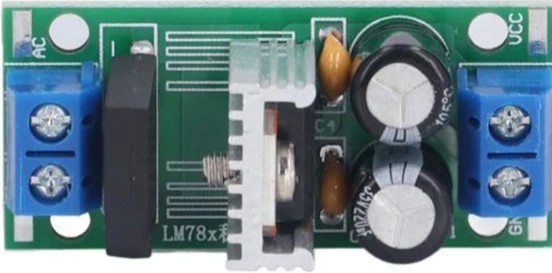
7805 5V Linear Regulator Module (1.5A) Documentation
1. Introduction
The 7805 5V Linear Regulator Module is a widely used voltage regulator designed to provide a stable 5V DC output. It is capable of delivering up to 1.5A of current, making it ideal for powering microcontrollers, sensors, and other electronic devices that require a steady 5V supply. The 7805 is part of the 78xx series of voltage regulators, which are known for their simplicity, reliability, and ease of use.
Common Applications:
- Powering microcontrollers (e.g., Arduino, Raspberry Pi, ESP32)
- Regulating voltage for sensors and modules
- Battery-powered projects requiring a stable 5V output
- DIY electronics and prototyping
- Power supply circuits for small appliances
2. Technical Specifications
The following table outlines the key technical details of the 7805 regulator module:
| Parameter | Value |
|---|---|
| Input Voltage Range | 7V to 35V |
| Output Voltage | 5V ± 2% |
| Maximum Output Current | 1.5A |
| Dropout Voltage | 2V to 2.5V (typical) |
| Quiescent Current | 5mA (typical) |
| Operating Temperature | -40°C to +125°C |
| Package Type | TO-220 (commonly used) |
| Protection Features | Overheat, Overcurrent, Short-circuit |
Pin Configuration
The 7805 regulator typically comes in a TO-220 package with three pins. The pinout is as follows:
| Pin Number | Pin Name | Description |
|---|---|---|
| 1 | Input (VIN) | Connect to the unregulated input voltage |
| 2 | Ground (GND) | Common ground for input and output |
| 3 | Output (VOUT) | Regulated 5V output |
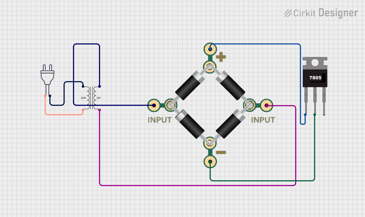
3. Usage Instructions
Basic Circuit Configuration
To use the 7805 regulator module, follow these steps:
Connect the Input Voltage (VIN):
- Provide an input voltage between 7V and 35V to the
VINpin. - Ensure the input voltage is at least 2V higher than the desired 5V output (to account for dropout voltage).
- Provide an input voltage between 7V and 35V to the
Connect the Ground (GND):
- Connect the
GNDpin to the ground of your circuit.
- Connect the
Connect the Output (VOUT):
- The
VOUTpin provides a stable 5V output. Connect this to the load or device requiring 5V.
- The
Add Capacitors for Stability:
- Place a 0.33µF capacitor between
VINandGND(input side). - Place a 0.1µF capacitor between
VOUTandGND(output side). - These capacitors help filter noise and improve stability.
- Place a 0.33µF capacitor between
Example Circuit Diagram
   Input Voltage (7V-35V)
          |
          +----[0.33µF]----+
          |                |
         VIN              GND
          |                |
         7805 Regulator    |
          |                |
         VOUT             GND
          |                |
          +----[0.1µF]-----+
          |
   Regulated 5V Output
Important Considerations:
- Heat Dissipation: The 7805 can generate significant heat, especially at high input voltages or currents. Use a heat sink to prevent overheating.
- Current Limitation: Do not exceed the maximum output current of 1.5A.
- Input Voltage Range: Ensure the input voltage is within the specified range (7V to 35V).
- Protection Features: The 7805 includes built-in protection against overcurrent, overheating, and short circuits, but proper design practices should still be followed.
4. Example with Arduino UNO
The 7805 regulator can be used to power an Arduino UNO by providing a stable 5V supply. Below is an example of how to connect the 7805 to an Arduino UNO:
Circuit Connections:
- Connect the
VINpin of the 7805 to a 9V battery or a DC power source. - Connect the
GNDpin of the 7805 to the ground of the Arduino UNO. - Connect the
VOUTpin of the 7805 to the 5V pin of the Arduino UNO.
Example Code:
The following Arduino code demonstrates a simple LED blinking program powered by the 7805 regulator:
// Simple LED Blink Example
// Ensure the Arduino is powered via the 7805 regulator module

const int ledPin = 13; // Built-in LED pin on Arduino UNO

void setup() {
  pinMode(ledPin, OUTPUT); // Set the LED pin as an output
}

void loop() {
  digitalWrite(ledPin, HIGH); // Turn the LED on
  delay(1000);                // Wait for 1 second
  digitalWrite(ledPin, LOW);  // Turn the LED off
  delay(1000);                // Wait for 1 second
}
5. Troubleshooting and FAQs
Common Issues and Solutions:
| Issue | Possible Cause | Solution |
|---|---|---|
| Output voltage is not 5V | Input voltage is too low | Ensure input voltage is at least 7V |
| Regulator overheating | High input voltage or current draw | Use a heat sink or reduce input voltage |
| No output voltage | Incorrect wiring or damaged regulator | Check connections and replace the module |
| Output voltage fluctuates | Missing or insufficient capacitors | Add 0.33µF and 0.1µF capacitors |
Frequently Asked Questions:
Can I use the 7805 to power a 3.3V device?
- No, the 7805 provides a fixed 5V output. Use a 3.3V regulator (e.g., 7833) for 3.3V devices.
What happens if I exceed the maximum current rating?
- The 7805 has built-in overcurrent protection, but exceeding 1.5A may cause the regulator to shut down or overheat.
Can I use the 7805 without capacitors?
- While the 7805 may work without capacitors, it is highly recommended to use them for stability and noise reduction.
Is the 7805 suitable for battery-powered projects?
- Yes, but ensure the battery voltage is within the input range (7V-35V) and consider the dropout voltage.
6. Conclusion
The 7805 5V Linear Regulator Module is a reliable and versatile component for providing a stable 5V output in a wide range of electronic projects. By following the recommended usage instructions and best practices, you can ensure optimal performance and longevity of the regulator. Whether you're powering an Arduino UNO or building a custom circuit, the 7805 is a dependable choice for voltage regulation.
Explore Projects Built with 7805 5V Linear regulator module 1.5A


Explore Projects Built with 7805 5V Linear regulator module 1.5A