How to Use Adafruit Mini 8x8 LED Matrix Backpack Red: Examples, Pinouts, and Specs
Introduction
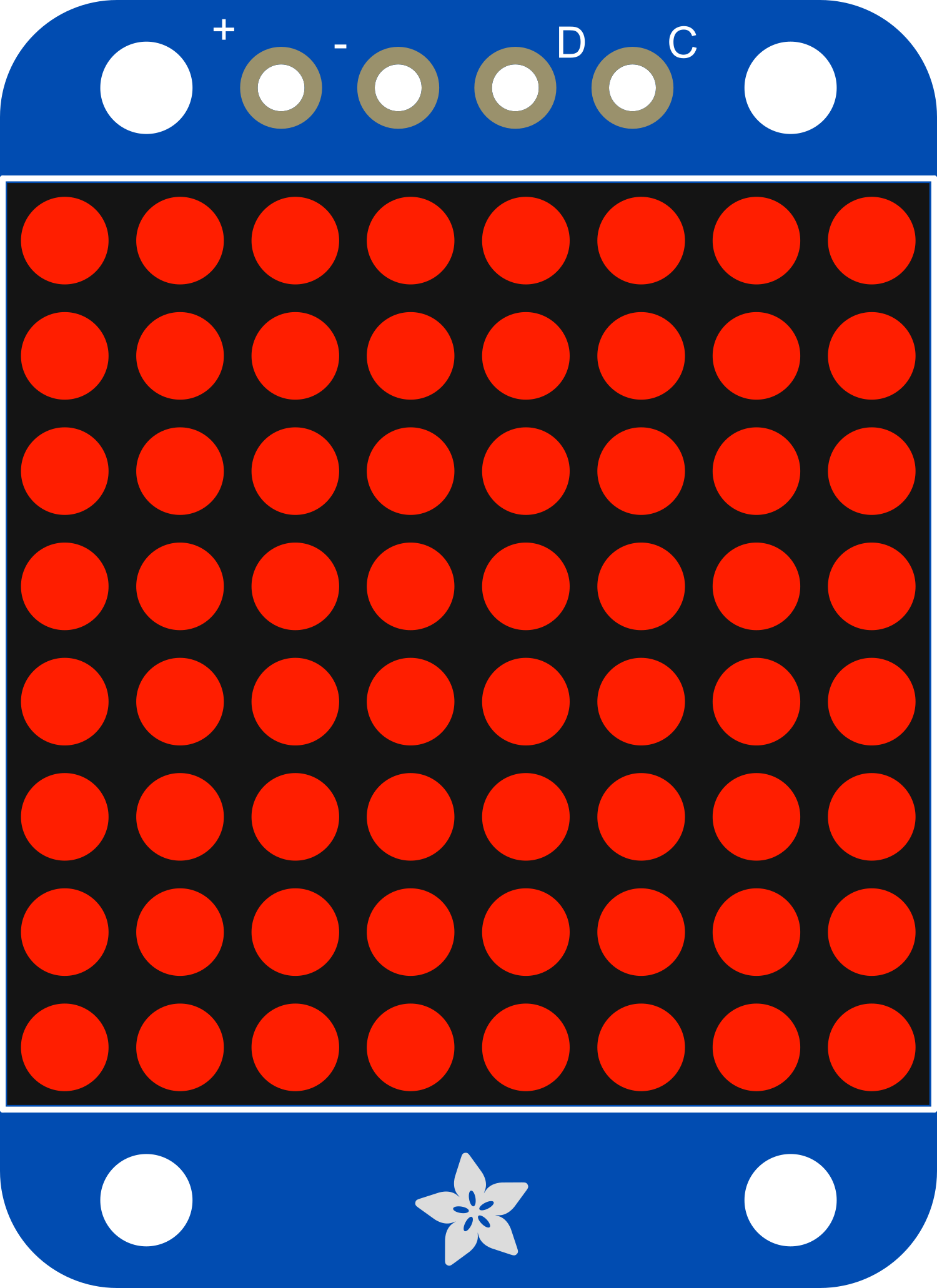
The Adafruit Mini 8x8 LED Matrix Backpack Red is a versatile and compact electronic component designed to control an 8x8 matrix of red LEDs. This module simplifies the process of driving multiple LEDs by integrating a driver chip that communicates via I2C interface. It is ideal for creating displays for simple graphics, text, and animations.
Explore Projects Built with Adafruit Mini 8x8 LED Matrix Backpack Red


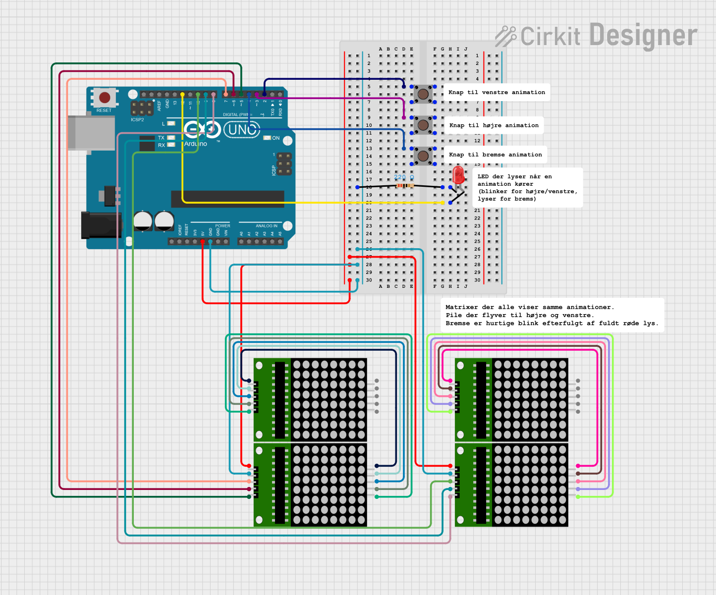
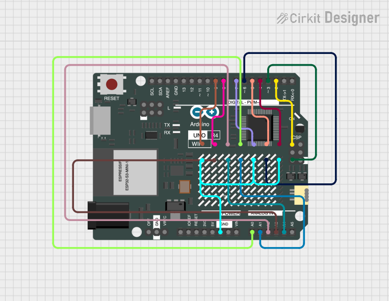
Explore Projects Built with Adafruit Mini 8x8 LED Matrix Backpack Red
Common Applications and Use Cases
- Digital signage and message boards
- Gaming displays and scoreboards
- Wearable electronics and badges
- Educational projects and DIY electronics
Technical Specifications
Key Technical Details
- Operating Voltage: 4.5V to 5.5V
- Max Current (per LED): 30mA
- Max Current (for all LEDs): 500mA
- Communication: I2C interface
- I2C Addresses: Selectable between 0x70-0x77
Pin Configuration and Descriptions
| Pin Number | Name | Description |
|---|---|---|
| 1 | GND | Ground connection |
| 2 | VCC | Power supply (4.5V to 5.5V) |
| 3 | SDA | I2C Data line |
| 4 | SCL | I2C Clock line |
| 5 | ADDR | Address selection pin |
| 6 | RST | Reset pin (optional use) |
Usage Instructions
How to Use the Component in a Circuit
- Connect the VCC pin to a 5V power supply.
- Connect the GND pin to the ground of the power supply.
- Connect the SDA and SCL pins to the I2C data and clock lines, respectively.
- If using multiple matrices, connect the ADDR pin to ground or VCC to set the I2C address.
- Optionally, connect the RST pin to a digital output on your microcontroller if you wish to use the reset feature.
Important Considerations and Best Practices
- Ensure that the power supply does not exceed 5.5V to prevent damage to the LEDs.
- Limit the current to 30mA per LED to avoid overheating and ensure longevity.
- Use pull-up resistors on the I2C lines if they are not already present on your microcontroller board.
- When daisy-chaining multiple matrices, ensure that the total current does not exceed the power supply capabilities.
Example Code for Arduino UNO
#include <Wire.h>
#include <Adafruit_GFX.h>
#include <Adafruit_LEDBackpack.h>

Adafruit_8x8matrix matrix = Adafruit_8x8matrix();

void setup() {
  matrix.begin(0x70); // Initialize the matrix with its I2C address
  matrix.setBrightness(10); // Set the brightness to a medium level
}

void loop() {
  matrix.clear(); // Clear the matrix display
  matrix.drawPixel(4, 4, LED_ON); // Turn on a single LED at (x=4, y=4)
  matrix.writeDisplay(); // Update the display with the changes
  delay(500); // Wait for half a second
  matrix.clear(); // Clear the display again
  matrix.writeDisplay(); // Update the display
  delay(500); // Wait for half a second
}
Troubleshooting and FAQs
Common Issues Users Might Face
- LEDs not lighting up: Check the power supply connections and ensure that the I2C lines are properly connected.
- Dim or flickering LEDs: Verify that the power supply is stable and that the brightness is set correctly in the code.
- Incorrect LED patterns: Ensure that the correct I2C address is used in the code if multiple matrices are connected.
Solutions and Tips for Troubleshooting
- Double-check all connections, especially the I2C lines, for loose wires or poor solder joints.
- Use a multimeter to verify that the power supply is delivering the correct voltage.
- If using multiple matrices, make sure each has a unique I2C address.
FAQs
Q: Can I use this matrix with a 3.3V system? A: While the matrix is rated for 4.5V to 5.5V, it may work at 3.3V with reduced brightness. However, this is not officially supported and may lead to unpredictable behavior.
Q: How many matrices can I chain together? A: You can chain up to 8 matrices together, as there are 8 selectable I2C addresses from 0x70 to 0x77.
Q: Can I control individual LED brightness? A: No, the brightness control affects the entire matrix. Individual LED brightness control is not supported.
This documentation provides a comprehensive guide to using the Adafruit Mini 8x8 LED Matrix Backpack Red. For further assistance or advanced projects, consult the Adafruit forums or technical support.