How to Use PressureSensor: Examples, Pinouts, and Specs
Introduction
The DFRobot ICP-1011 Pressure Sensor is a high-precision device designed to measure the pressure of gases or liquids and convert it into a readable signal. This sensor is based on MEMS (Micro-Electro-Mechanical Systems) technology, offering exceptional accuracy and low power consumption. It is ideal for applications requiring precise pressure measurements, such as weather monitoring, altitude detection, and industrial process control.
Explore Projects Built with PressureSensor

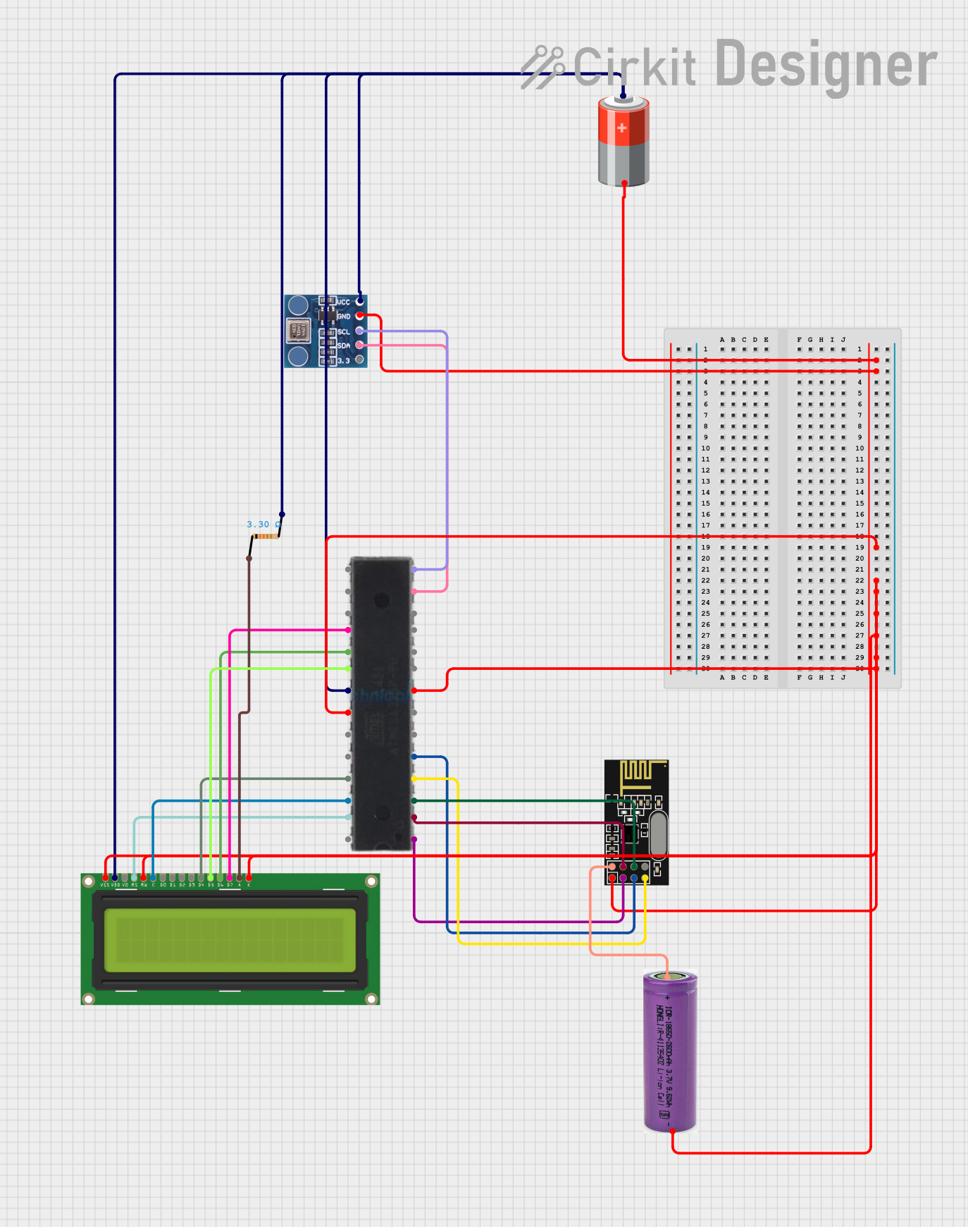
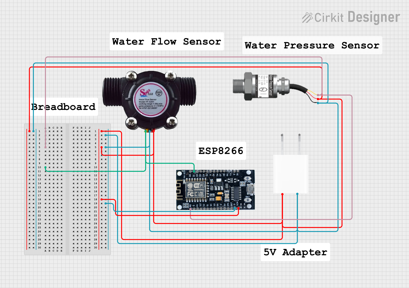
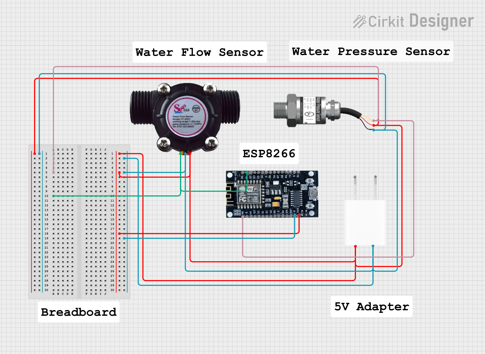
Explore Projects Built with PressureSensor
Common Applications
- Weather stations and barometric pressure monitoring
- Altitude measurement in drones and GPS systems
- Industrial process control and fluid dynamics
- HVAC (Heating, Ventilation, and Air Conditioning) systems
- Wearable devices for health monitoring
Technical Specifications
The following table outlines the key technical details of the DFRobot ICP-1011 Pressure Sensor:
| Parameter | Value |
|---|---|
| Operating Voltage | 1.8V to 3.6V |
| Operating Current | 1.3 µA (low-power mode) |
| Pressure Range | 300 hPa to 1260 hPa |
| Pressure Resolution | 1 Pa |
| Temperature Range | -40°C to +85°C |
| Communication Protocol | I²C |
| Dimensions | 2.0 mm x 2.5 mm x 0.8 mm |
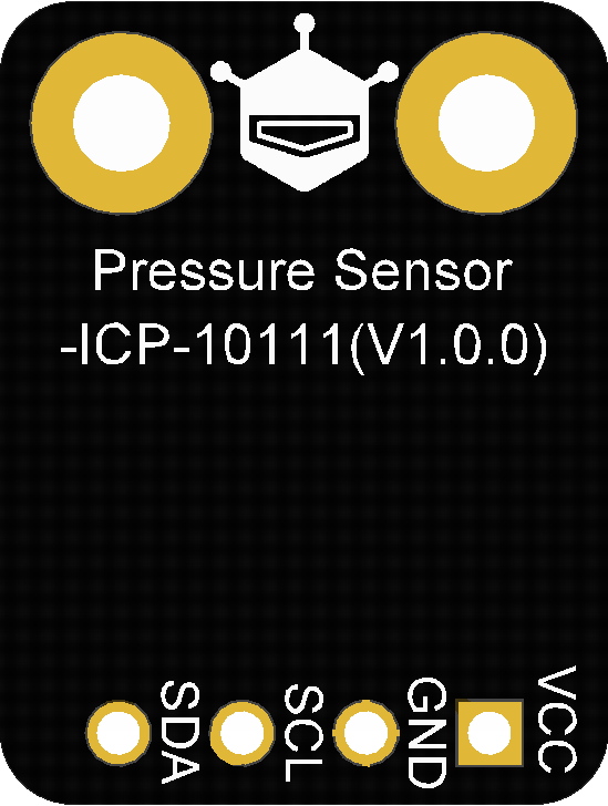
Pin Configuration
The ICP-1011 is typically mounted on a breakout board for ease of use. Below is the pin configuration for the sensor:
| Pin Name | Description |
|---|---|
| VCC | Power supply (1.8V to 3.6V) |
| GND | Ground |
| SDA | I²C data line |
| SCL | I²C clock line |
| INT | Interrupt pin (optional, for advanced use) |
Usage Instructions
Connecting the ICP-1011 to a Circuit
- Power Supply: Connect the VCC pin to a 3.3V power source (or 1.8V if supported by your system) and the GND pin to ground.
- I²C Communication: Connect the SDA and SCL pins to the corresponding I²C pins on your microcontroller. For an Arduino UNO, connect:
- SDA to A4
- SCL to A5
- Pull-Up Resistors: Ensure that the I²C lines (SDA and SCL) have pull-up resistors (typically 4.7 kΩ) if not already included on the breakout board.
Sample Code for Arduino UNO
Below is an example of how to interface the ICP-1011 with an Arduino UNO using the I²C protocol:
#include <Wire.h>

// ICP-1011 I2C address
#define ICP1011_ADDR 0x63

void setup() {
  Wire.begin(); // Initialize I2C communication
  Serial.begin(9600); // Start serial communication for debugging

  // Check if the sensor is connected
  Wire.beginTransmission(ICP1011_ADDR);
  if (Wire.endTransmission() == 0) {
    Serial.println("ICP-1011 detected!");
  } else {
    Serial.println("ICP-1011 not detected. Check connections.");
    while (1); // Halt execution if sensor is not found
  }
}

void loop() {
  // Request pressure data from the sensor
  Wire.beginTransmission(ICP1011_ADDR);
  Wire.write(0x00); // Command to read pressure (example command)
  Wire.endTransmission();

  Wire.requestFrom(ICP1011_ADDR, 2); // Request 2 bytes of data
  if (Wire.available() == 2) {
    uint16_t pressure = Wire.read() << 8 | Wire.read(); // Combine bytes
    Serial.print("Pressure: ");
    Serial.print(pressure);
    Serial.println(" Pa");
  } else {
    Serial.println("Failed to read pressure data.");
  }

  delay(1000); // Wait 1 second before the next reading
}
Important Considerations
- Power Supply: Ensure the sensor operates within its specified voltage range to avoid damage.
- I²C Address: The default I²C address of the ICP-1011 is
0x63. Verify this in the datasheet or with a scanner if using multiple devices. - Environmental Factors: Avoid exposing the sensor to extreme conditions (e.g., high humidity or corrosive gases) that could affect its performance.
Troubleshooting and FAQs
Common Issues
Sensor Not Detected
- Cause: Incorrect wiring or I²C address mismatch.
- Solution: Double-check the connections and ensure the correct I²C address is used in the code.
Inaccurate Readings
- Cause: Environmental interference or improper calibration.
- Solution: Calibrate the sensor in a controlled environment and ensure it is not exposed to sudden temperature changes.
No Data Output
- Cause: Missing pull-up resistors on the I²C lines.
- Solution: Add 4.7 kΩ pull-up resistors to the SDA and SCL lines if not already present.
FAQs
Q: Can the ICP-1011 measure altitude?
A: Yes, the sensor can calculate altitude based on pressure readings, making it suitable for applications like drones and GPS systems.
Q: Is the sensor compatible with 5V systems?
A: The ICP-1011 operates at a maximum of 3.6V. Use a level shifter if interfacing with a 5V system.
Q: How do I improve measurement accuracy?
A: Place the sensor in a stable environment, avoid vibrations, and use software filtering techniques to smooth out noise in the readings.