
How to Use SMD RGB LED (WS2812): Examples, Pinouts, and Specs
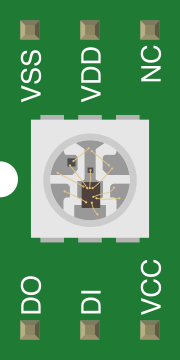
 Design with SMD RGB LED (WS2812) in Cirkit Designer
Introduction
The SMD RGB LED (WS2812) is a compact, addressable RGB LED that integrates red, green, and blue LEDs into a single package. It features an integrated control circuit, allowing for precise control of color and brightness. The WS2812 is widely used in applications requiring programmable lighting effects, such as decorative lighting, displays, and custom electronics projects. Its addressable nature enables users to control multiple LEDs individually using a single data line, making it ideal for creating dynamic and complex lighting patterns.
Explore Projects Built with SMD RGB LED (WS2812)
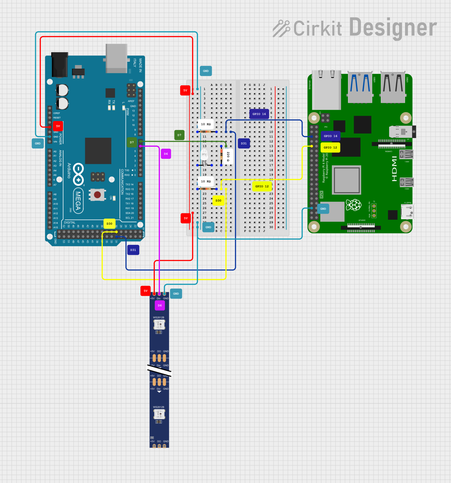 Open Project in Cirkit Designer
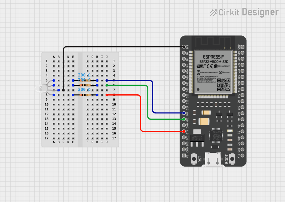 Open Project in Cirkit Designer
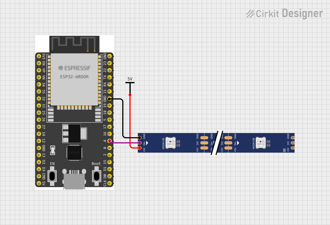 Open Project in Cirkit Designer
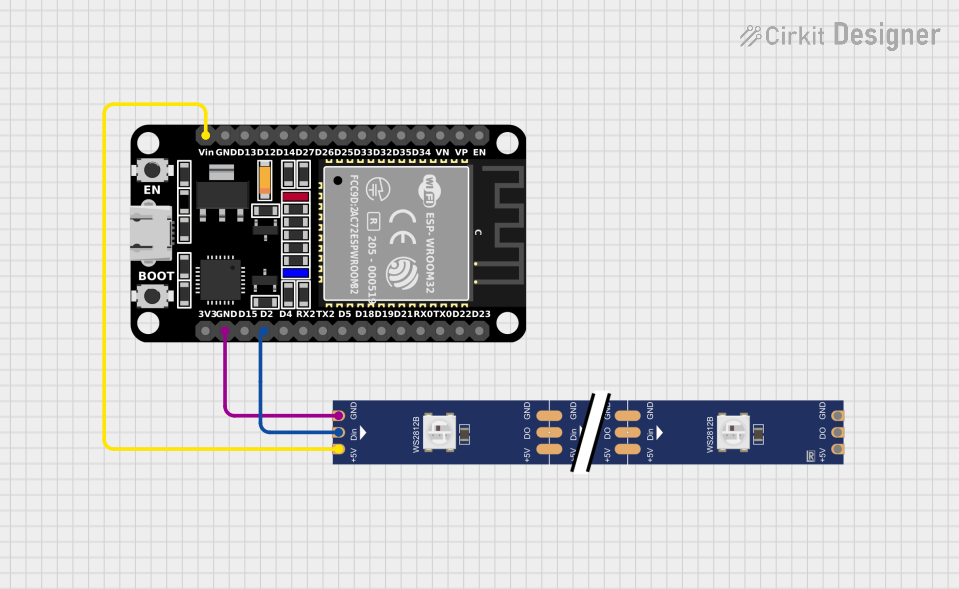 Open Project in Cirkit Designer
Explore Projects Built with SMD RGB LED (WS2812)
Open Project in Cirkit DesignerOpen Project in Cirkit DesignerOpen Project in Cirkit DesignerOpen Project in Cirkit DesignerCommon Applications
- LED strips for decorative and architectural lighting
- Wearable electronics and art installations
- Custom displays and signage
- Gaming peripherals and PC case lighting
- Robotics and hobbyist projects
Technical Specifications
The WS2812 SMD RGB LED combines an RGB LED and a driver IC in a single package. Below are its key technical details:
Key Specifications
| Parameter | Value |
|---|---|
| Operating Voltage | 3.5V to 5.3V |
| Operating Current | ~20mA per color channel |
| Maximum Power | ~60mW per LED |
| Communication Protocol | Single-wire (serial) |
| Data Transfer Rate | Up to 800kbps |
| LED Color Depth | 8 bits per channel (24-bit) |
| Viewing Angle | 120° |
| Operating Temperature | -25°C to +80°C |
| Package Size | 5mm x 5mm x 1.5mm |
Pin Configuration
The WS2812 has four pins, as described in the table below:
| Pin Name | Pin Number | Description |
|---|---|---|
| VDD | 1 | Power supply (3.5V to 5.3V) |
| GND | 2 | Ground connection |
| DIN | 3 | Data input for receiving control signals |
| DOUT | 4 | Data output for chaining additional LEDs |
Usage Instructions
How to Use the WS2812 in a Circuit
- Power Supply: Connect the VDD pin to a 5V power source and the GND pin to ground. Ensure the power supply can handle the total current draw of all LEDs in the chain.
- Data Line: Connect the DIN pin to a microcontroller's digital output pin. Use a resistor (330-500Ω) in series with the data line to reduce noise and protect the LED.
- Capacitor: Place a 0.1µF ceramic capacitor between VDD and GND near the LED to stabilize the power supply.
- Chaining LEDs: To chain multiple WS2812 LEDs, connect the DOUT pin of one LED to the DIN pin of the next LED.
Best Practices
- Use a level shifter if your microcontroller operates at 3.3V logic levels, as the WS2812 requires 5V logic for reliable operation.
- Avoid long data lines to minimize signal degradation. If necessary, use a buffer or repeater.
- Ensure proper heat dissipation if driving a large number of LEDs.
Example Code for Arduino UNO
Below is an example of how to control a WS2812 LED strip using the Arduino UNO and the Adafruit NeoPixel library:
#include <Adafruit_NeoPixel.h>

// Define the number of LEDs in the strip
#define NUM_LEDS 8

// Define the pin connected to the DIN of the WS2812
#define DATA_PIN 6

// Create a NeoPixel object
Adafruit_NeoPixel strip = Adafruit_NeoPixel(NUM_LEDS, DATA_PIN, NEO_GRB + NEO_KHZ800);

void setup() {
  strip.begin();           // Initialize the NeoPixel library
  strip.show();            // Turn off all LEDs initially
}

void loop() {
  // Set the first LED to red
  strip.setPixelColor(0, strip.Color(255, 0, 0)); // Red: 255, Green: 0, Blue: 0
  strip.show();           // Update the LED strip
  delay(500);             // Wait for 500ms

  // Set the first LED to green
  strip.setPixelColor(0, strip.Color(0, 255, 0)); // Red: 0, Green: 255, Blue: 0
  strip.show();           // Update the LED strip
  delay(500);             // Wait for 500ms

  // Set the first LED to blue
  strip.setPixelColor(0, strip.Color(0, 0, 255)); // Red: 0, Green: 0, Blue: 255
  strip.show();           // Update the LED strip
  delay(500);             // Wait for 500ms
}
Notes
- Install the Adafruit NeoPixel library via the Arduino Library Manager before uploading the code.
- Adjust
NUM_LEDSto match the number of LEDs in your setup.
Troubleshooting and FAQs
Common Issues
LEDs Not Lighting Up
- Check the power supply voltage and current capacity.
- Verify the data line connection and ensure the microcontroller pin is configured correctly.
- Ensure the DIN pin is receiving a valid signal.
Flickering or Incorrect Colors
- Use a resistor (330-500Ω) on the data line to reduce noise.
- Add a capacitor (0.1µF) across VDD and GND to stabilize the power supply.
- Ensure the data signal is clean and not degraded by long wires.
Only the First LED Works
- Check the connection between the DOUT pin of the first LED and the DIN pin of the next LED.
- Ensure the data signal timing matches the WS2812 protocol.
FAQs
Q: Can I power the WS2812 with a 3.3V power supply?
A: While the WS2812 can operate at 3.5V, it is recommended to use a 5V power supply for optimal performance. If using a 3.3V microcontroller, a level shifter is required for the data line.
Q: How many LEDs can I chain together?
A: Theoretically, you can chain hundreds of LEDs, but the practical limit depends on the power supply capacity and signal integrity. Use a power injection point for long chains to prevent voltage drop.
Q: Can I control the WS2812 without a library?
A: Yes, but it requires precise timing to generate the WS2812 protocol. Using a library like Adafruit NeoPixel simplifies the process significantly.