How to Use OMGS3: Examples, Pinouts, and Specs
Introduction
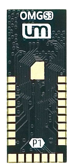
The OMGS3 is a versatile microcontroller designed for a wide range of applications, particularly in the Internet of Things (IoT) and smart device domains. It features integrated Wi-Fi and Bluetooth capabilities, enabling seamless wireless communication. With its powerful processing capabilities and low power consumption, the OMGS3 is an excellent choice for projects requiring connectivity, automation, and real-time data processing.
Explore Projects Built with OMGS3

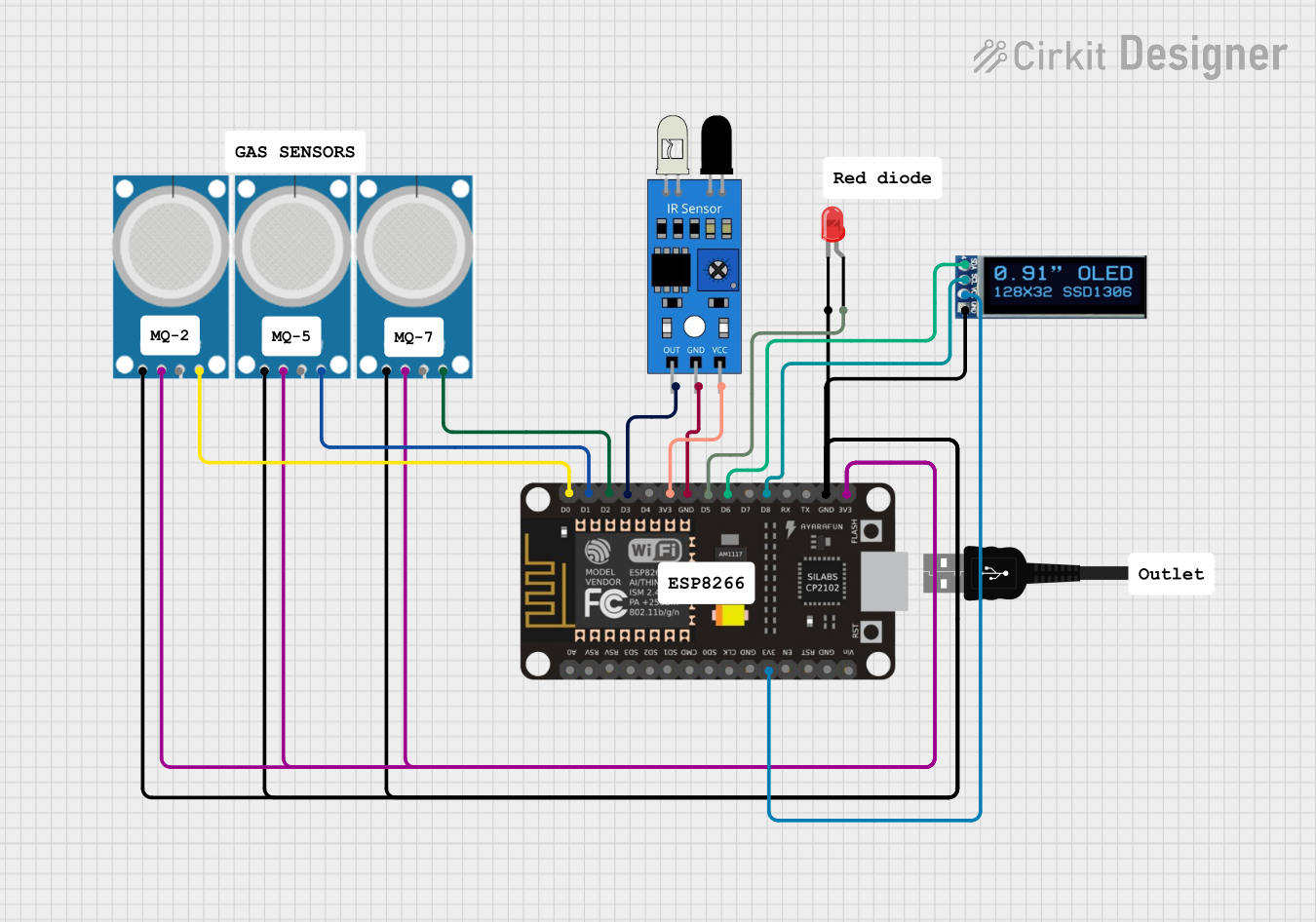


Explore Projects Built with OMGS3
Common Applications and Use Cases
- IoT devices such as smart home systems, wearables, and environmental sensors
- Wireless communication hubs and gateways
- Automation systems for industrial and consumer applications
- Prototyping and development of connected devices
- Educational projects and learning platforms for embedded systems
Technical Specifications
The OMGS3 microcontroller is packed with features that make it suitable for a variety of applications. Below are its key technical specifications:
General Specifications
| Parameter | Value |
|---|---|
| Processor | 32-bit RISC CPU |
| Clock Speed | Up to 240 MHz |
| Flash Memory | 4 MB |
| SRAM | 512 KB |
| Wireless Connectivity | Wi-Fi 802.11 b/g/n, Bluetooth 5.0 |
| Operating Voltage | 3.3V |
| Power Consumption | Low-power modes available |
| GPIO Pins | 34 |
| Communication Protocols | UART, SPI, I2C, PWM, ADC |
Pin Configuration and Descriptions
The OMGS3 has a total of 34 GPIO pins, which can be configured for various functions. Below is a table describing the key pins:
| Pin Number | Pin Name | Functionality |
|---|---|---|
| 1 | GND | Ground |
| 2 | 3V3 | 3.3V Power Supply |
| 3 | EN | Enable Pin (Active High) |
| 4 | GPIO0 | General Purpose I/O, ADC, PWM |
| 5 | GPIO1 | General Purpose I/O, UART TX |
| 6 | GPIO2 | General Purpose I/O, ADC, PWM |
| 7 | GPIO3 | General Purpose I/O, UART RX |
| 8 | GPIO4 | General Purpose I/O, I2C SDA |
| 9 | GPIO5 | General Purpose I/O, I2C SCL |
| 10 | GPIO6-11 | Reserved for Flash Memory Interface |
| 12 | GPIO12 | General Purpose I/O, ADC, PWM |
| 13 | GPIO13 | General Purpose I/O, ADC, PWM |
| 14 | GPIO14 | General Purpose I/O, SPI CLK |
| 15 | GPIO15 | General Purpose I/O, SPI CS |
| 16 | GPIO16 | General Purpose I/O, SPI MOSI |
| 17 | GPIO17 | General Purpose I/O, SPI MISO |
| 18-34 | GPIO18-34 | General Purpose I/O, ADC, PWM |
Usage Instructions
How to Use the OMGS3 in a Circuit
- Powering the OMGS3: Connect the 3V3 pin to a 3.3V power source and the GND pin to ground.
- Programming the Microcontroller: Use a USB-to-serial adapter to upload code to the OMGS3. Ensure the EN pin is pulled high during operation.
- Connecting Peripherals: Use the GPIO pins to connect sensors, actuators, or other peripherals. Configure the pins in your code for the desired functionality (e.g., input, output, ADC, PWM).
- Wireless Communication: Utilize the integrated Wi-Fi and Bluetooth modules for wireless data transmission. Libraries such as
WiFi.handBluetoothSerial.hcan simplify development.
Important Considerations and Best Practices
- Voltage Levels: Ensure all connected peripherals operate at 3.3V logic levels to avoid damaging the microcontroller.
- Pin Multiplexing: Some pins have multiple functions (e.g., ADC, PWM, UART). Refer to the datasheet to avoid conflicts.
- Heat Management: While the OMGS3 is efficient, prolonged high-performance operation may generate heat. Consider adding a heatsink or ensuring proper ventilation.
- Firmware Updates: Keep the firmware updated to ensure compatibility with the latest libraries and features.
Example Code for Arduino UNO Integration
Below is an example of how to use the OMGS3 with an Arduino IDE to connect to a Wi-Fi network:
#include <WiFi.h> // Include the Wi-Fi library

const char* ssid = "Your_SSID";       // Replace with your Wi-Fi network name
const char* password = "Your_Password"; // Replace with your Wi-Fi password

void setup() {
  Serial.begin(115200); // Initialize serial communication at 115200 baud
  WiFi.begin(ssid, password); // Start connecting to Wi-Fi

  Serial.print("Connecting to Wi-Fi");
  while (WiFi.status() != WL_CONNECTED) {
    delay(500); // Wait for connection
    Serial.print(".");
  }
  Serial.println("\nConnected to Wi-Fi!");
  Serial.print("IP Address: ");
  Serial.println(WiFi.localIP()); // Print the assigned IP address
}

void loop() {
  // Add your main code here
}
Troubleshooting and FAQs
Common Issues and Solutions
The OMGS3 is not powering on:
- Ensure the 3V3 pin is connected to a stable 3.3V power source.
- Verify that the EN pin is pulled high.
Unable to upload code:
- Check the USB-to-serial adapter connection and ensure the correct COM port is selected.
- Ensure the microcontroller is in programming mode (refer to the datasheet for specific instructions).
Wi-Fi connection fails:
- Double-check the SSID and password in your code.
- Ensure the Wi-Fi network is within range and operational.
Bluetooth not working:
- Verify that the Bluetooth module is enabled in your code.
- Check for interference from other devices operating on the same frequency.
Tips for Troubleshooting
- Use a multimeter to check voltage levels on the power and GPIO pins.
- Monitor the serial output for error messages or debugging information.
- Refer to the OMGS3 datasheet for detailed pin configurations and electrical characteristics.
By following this documentation, you can effectively utilize the OMGS3 microcontroller in your projects and troubleshoot common issues with ease.