
How to Use lm2596 Step-Down Buck DC/DC: Examples, Pinouts, and Specs
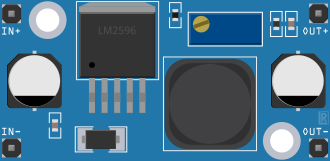
 Design with lm2596 Step-Down Buck DC/DC in Cirkit Designer
Introduction
The LM2596 is a step-down (buck) voltage regulator designed to efficiently convert a higher DC voltage to a lower DC voltage. Manufactured by CN China, this versatile component is capable of delivering up to 3A of output current. It features built-in thermal shutdown and current limiting for enhanced protection, making it a reliable choice for various applications.
Explore Projects Built with lm2596 Step-Down Buck DC/DC
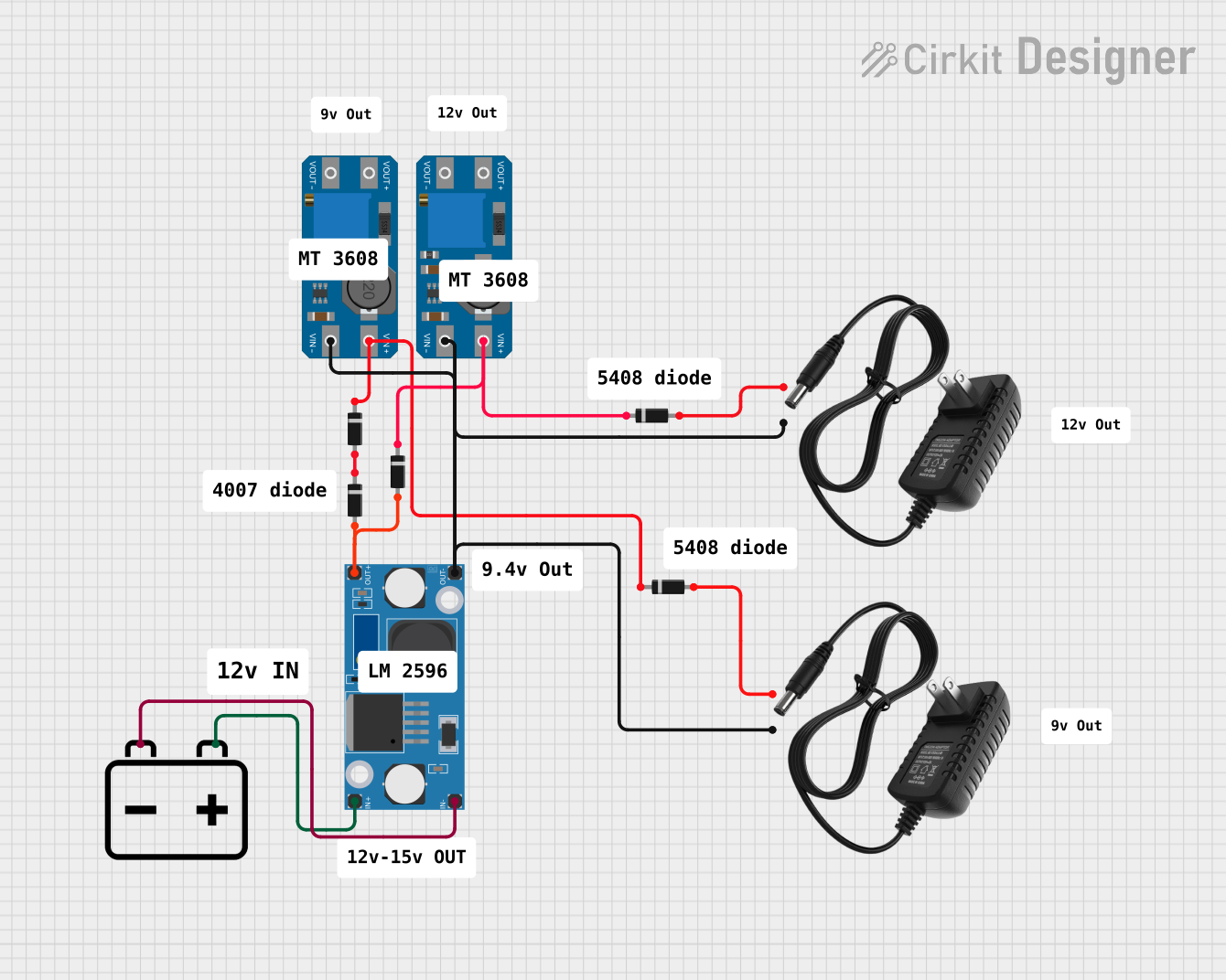 Open Project in Cirkit Designer
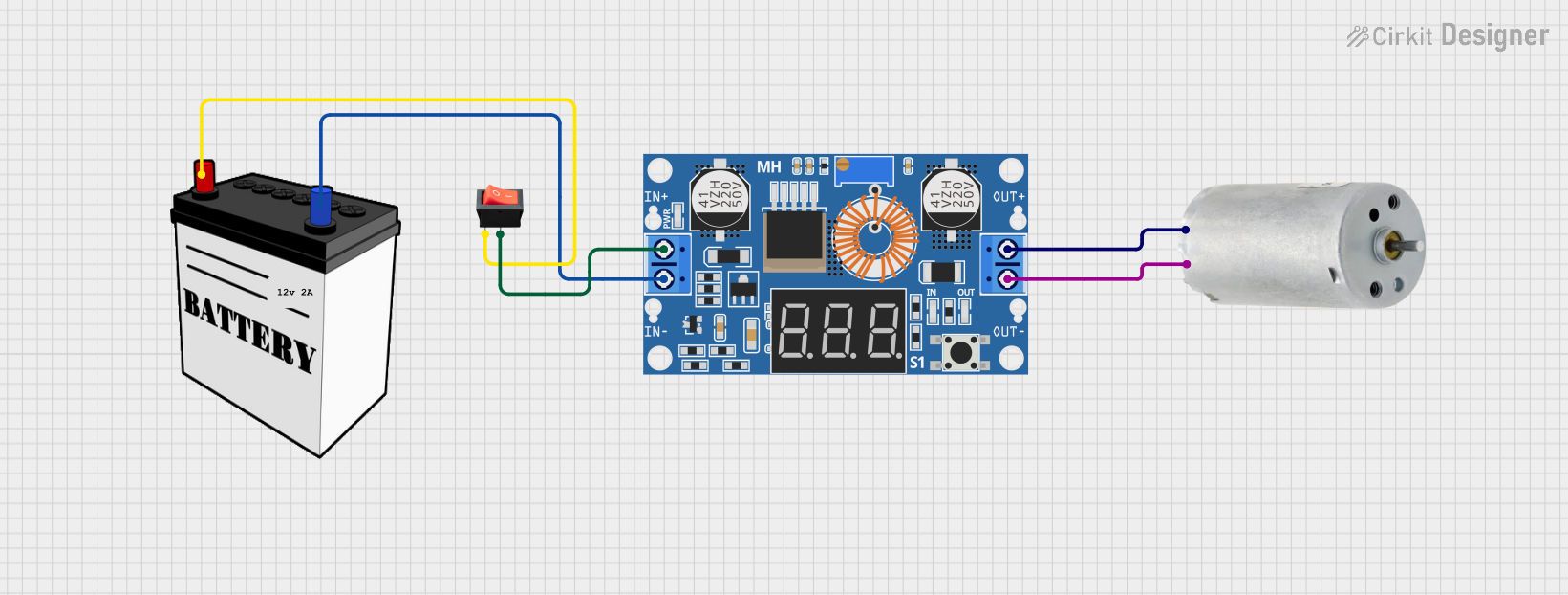 Open Project in Cirkit Designer
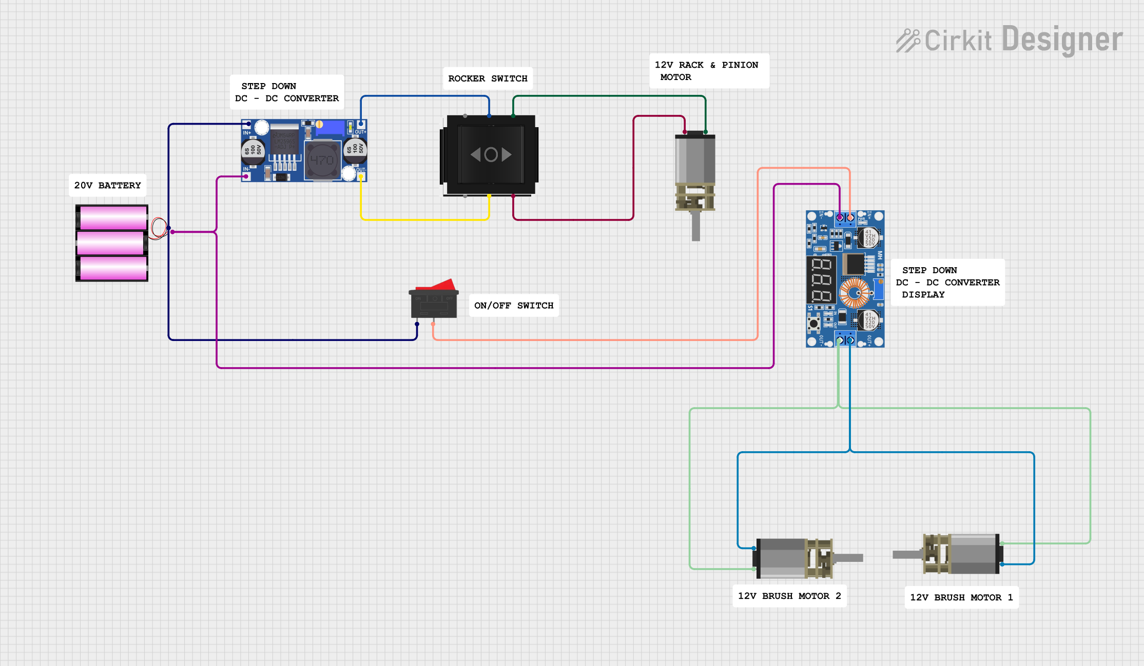 Open Project in Cirkit Designer
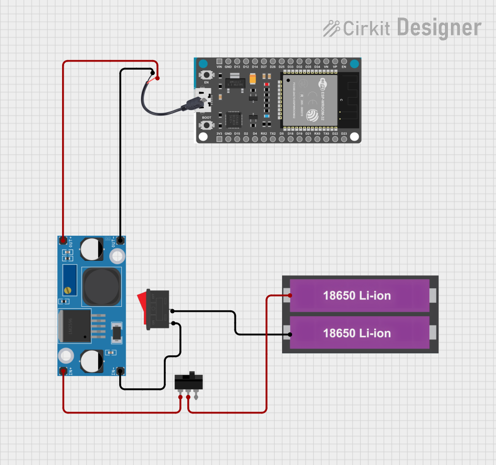 Open Project in Cirkit Designer
Explore Projects Built with lm2596 Step-Down Buck DC/DC
Open Project in Cirkit DesignerOpen Project in Cirkit DesignerOpen Project in Cirkit DesignerOpen Project in Cirkit DesignerCommon Applications
- Power supply circuits for microcontrollers, sensors, and modules
- Battery-powered devices requiring regulated voltage
- LED drivers and lighting systems
- Industrial and automotive electronics
- DIY electronics projects and prototyping
Technical Specifications
Key Technical Details
| Parameter | Value |
|---|---|
| Input Voltage Range | 4.5V to 40V |
| Output Voltage Range | 1.23V to 37V (adjustable) |
| Output Current | Up to 3A |
| Efficiency | Up to 92% |
| Switching Frequency | 150 kHz (typical) |
| Thermal Shutdown | Yes |
| Current Limiting | Yes |
| Operating Temperature | -40°C to +125°C |
| Package Type | TO-220 or TO-263 |
Pin Configuration and Descriptions
TO-220 Package Pinout
| Pin Number | Pin Name | Description |
|---|---|---|
| 1 | VIN | Input voltage (4.5V to 40V) |
| 2 | VOUT | Regulated output voltage (1.23V to 37V) |
| 3 | GND | Ground connection |
| 4 | Feedback | Voltage feedback for output regulation |
| 5 | ON/OFF | Enable/disable pin (active low) |
TO-263 Package Pinout
| Pin Number | Pin Name | Description |
|---|---|---|
| 1 | VIN | Input voltage (4.5V to 40V) |
| 2 | VOUT | Regulated output voltage (1.23V to 37V) |
| 3 | GND | Ground connection |
| 4 | Feedback | Voltage feedback for output regulation |
| Tab | GND | Ground connection (thermal pad) |
Usage Instructions
How to Use the LM2596 in a Circuit
- Input Voltage: Connect the input voltage (4.5V to 40V) to the VIN pin. Ensure the input voltage is higher than the desired output voltage by at least 3V for proper regulation.
- Output Voltage: Connect the load to the VOUT pin. Use a multimeter to measure the output voltage and adjust the feedback resistor network to set the desired output voltage.
- Ground Connection: Connect the GND pin to the circuit ground.
- Feedback Resistor Network: Use a resistor divider network between the VOUT and Feedback pins to set the output voltage. The formula for output voltage is: [ V_{OUT} = V_{REF} \times \left(1 + \frac{R1}{R2}\right) ] where ( V_{REF} ) is 1.23V.
- Enable/Disable: If using the ON/OFF pin, connect it to GND to enable the regulator or leave it floating for continuous operation.
Important Considerations and Best Practices
- Input and Output Capacitors: Use appropriate input and output capacitors (e.g., 100µF electrolytic or ceramic) to ensure stable operation and reduce voltage ripple.
- Heat Dissipation: The LM2596 can generate heat during operation. Use a heatsink or ensure proper ventilation to prevent overheating.
- Inductor Selection: Choose an inductor with a current rating higher than the maximum load current and a low DC resistance (DCR) for optimal efficiency.
- PCB Layout: Minimize the trace length between the input/output capacitors and the LM2596 to reduce noise and improve stability.
Example: Using LM2596 with Arduino UNO
The LM2596 can be used to power an Arduino UNO by stepping down a 12V input to 5V. Below is an example circuit and Arduino code:
Circuit Connections
- Connect a 12V DC power source to the VIN pin of the LM2596.
- Adjust the feedback resistor network to set the output voltage to 5V.
- Connect the VOUT pin to the 5V pin of the Arduino UNO.
- Connect the GND pin of the LM2596 to the GND pin of the Arduino UNO.
Arduino Code Example
// Example code to blink an LED using Arduino UNO powered by LM2596
// Ensure the LM2596 output is set to 5V before connecting to Arduino

const int ledPin = 13; // Built-in LED pin on Arduino UNO

void setup() {
  pinMode(ledPin, OUTPUT); // Set LED pin as output
}

void loop() {
  digitalWrite(ledPin, HIGH); // Turn the LED on
  delay(1000);               // Wait for 1 second
  digitalWrite(ledPin, LOW);  // Turn the LED off
  delay(1000);               // Wait for 1 second
}
Troubleshooting and FAQs
Common Issues and Solutions
No Output Voltage:
- Check the input voltage; ensure it is within the specified range (4.5V to 40V).
- Verify the feedback resistor network is correctly configured.
- Ensure the ON/OFF pin is not connected to GND (if used).
Overheating:
- Ensure proper heat dissipation using a heatsink or adequate ventilation.
- Check for excessive load current; ensure it does not exceed 3A.
High Output Ripple:
- Use low-ESR capacitors for input and output filtering.
- Verify the inductor value and ensure it meets the design requirements.
Incorrect Output Voltage:
- Recalculate the feedback resistor values using the formula provided.
- Check for loose or incorrect connections in the circuit.
FAQs
Q: Can the LM2596 be used with a battery as the input source?
A: Yes, the LM2596 can be used with a battery as long as the input voltage is within the specified range (4.5V to 40V).
Q: What is the maximum efficiency of the LM2596?
A: The LM2596 can achieve an efficiency of up to 92%, depending on the input/output voltage and load conditions.
Q: Can the LM2596 output voltage be adjusted dynamically?
A: Yes, by using a variable resistor (potentiometer) in the feedback network, the output voltage can be adjusted dynamically.
Q: Is the LM2596 suitable for powering sensitive electronics?
A: Yes, but ensure proper filtering with capacitors to minimize output ripple and noise.