How to Use BMS: Examples, Pinouts, and Specs
Introduction
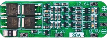
The 3S 20A BMS by HKN ENTERPRISES is a Battery Management System designed to manage and protect 3-cell lithium-ion or lithium-polymer battery packs. It ensures safe operation by monitoring the battery's state, balancing the cells, and protecting against overcharge, over-discharge, overcurrent, and short circuits. This BMS is ideal for applications requiring reliable battery management, such as electric vehicles, power tools, energy storage systems, and portable electronics.
Explore Projects Built with BMS


Explore Projects Built with BMS
Common Applications
- Electric bicycles and scooters
- Power banks and portable chargers
- Solar energy storage systems
- Uninterruptible Power Supplies (UPS)
- Robotics and IoT devices
Technical Specifications
The following table outlines the key technical details of the 3S 20A BMS:
| Parameter | Value |
|---|---|
| Manufacturer | HKN ENTERPRISES |
| Part ID | 3S 20A BMS |
| Battery Configuration | 3-series (3S) |
| Maximum Continuous Current | 20A |
| Overcharge Protection Voltage | 4.25V ± 0.05V per cell |
| Over-discharge Protection Voltage | 2.8V ± 0.05V per cell |
| Balance Current | 60mA |
| Operating Temperature | -40°C to 85°C |
| Dimensions | 50mm x 20mm x 3mm |
Pin Configuration and Descriptions
The 3S 20A BMS has the following pin configuration:
| Pin Name | Description |
|---|---|
| B+ | Battery pack positive terminal |
| B- | Battery pack negative terminal |
| P+ | Output positive terminal (to load or charger) |
| P- | Output negative terminal (to load or charger) |
| B1 | Connection to the positive terminal of Cell 1 |
| B2 | Connection to the positive terminal of Cell 2 |
| B3 | Connection to the positive terminal of Cell 3 |
Usage Instructions
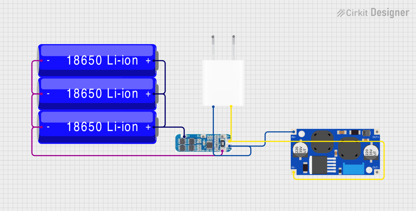
How to Use the 3S 20A BMS in a Circuit
Connect the Battery Pack:
- Connect the B+ pin to the positive terminal of the battery pack.
- Connect the B- pin to the negative terminal of the battery pack.
- Connect the B1, B2, and B3 pins to the positive terminals of the respective cells in the 3-cell series configuration.
Connect the Load and Charger:
- Connect the load's positive terminal to the P+ pin and the negative terminal to the P- pin.
- Similarly, connect the charger to the P+ and P- pins.
Verify Connections:
- Double-check all connections to ensure proper polarity and avoid short circuits.
Power On:
- Once all connections are secure, the BMS will automatically monitor and manage the battery pack.
Important Considerations and Best Practices
- Ensure the battery pack is configured as a 3-series (3S) pack. Using a different configuration may damage the BMS.
- Use batteries with similar capacities and charge levels to ensure proper balancing.
- Avoid exceeding the maximum continuous current rating of 20A.
- Ensure proper heat dissipation if the BMS operates near its maximum current rating.
- Do not expose the BMS to water or extreme environmental conditions.
Arduino UNO Integration Example
The 3S 20A BMS can be monitored using an Arduino UNO to read battery voltage levels. Below is an example code to measure the voltage of each cell using analog inputs:
// Arduino code to monitor 3S battery pack voltages using the 3S 20A BMS
// Connect the B1, B2, and B3 pins to analog inputs A0, A1, and A2 respectively.

const int cell1Pin = A0; // Pin connected to B1 (Cell 1 positive terminal)
const int cell2Pin = A1; // Pin connected to B2 (Cell 2 positive terminal)
const int cell3Pin = A2; // Pin connected to B3 (Cell 3 positive terminal)

void setup() {
  Serial.begin(9600); // Initialize serial communication
}

void loop() {
  // Read analog values from each cell
  int cell1Voltage = analogRead(cell1Pin);
  int cell2Voltage = analogRead(cell2Pin);
  int cell3Voltage = analogRead(cell3Pin);

  // Convert analog values to voltage (assuming 5V reference and 10-bit ADC)
  float voltage1 = (cell1Voltage * 5.0) / 1023.0;
  float voltage2 = (cell2Voltage * 5.0) / 1023.0;
  float voltage3 = (cell3Voltage * 5.0) / 1023.0;

  // Print voltages to the Serial Monitor
  Serial.print("Cell 1 Voltage: ");
  Serial.print(voltage1);
  Serial.println(" V");

  Serial.print("Cell 2 Voltage: ");
  Serial.print(voltage2);
  Serial.println(" V");

  Serial.print("Cell 3 Voltage: ");
  Serial.print(voltage3);
  Serial.println(" V");

  delay(1000); // Wait for 1 second before the next reading
}
Troubleshooting and FAQs
Common Issues and Solutions
BMS Not Powering On:
- Cause: Incorrect wiring or loose connections.
- Solution: Verify all connections, especially the B+ and B- terminals.
Overheating:
- Cause: Exceeding the maximum current rating of 20A.
- Solution: Reduce the load current or improve heat dissipation.
Uneven Cell Balancing:
- Cause: Cells with significantly different capacities or charge levels.
- Solution: Use cells with similar specifications and pre-balance them before connecting to the BMS.
Charger Not Working:
- Cause: Charger voltage exceeds the overcharge protection voltage.
- Solution: Use a charger with a voltage suitable for a 3S battery pack (e.g., 12.6V for lithium-ion).
FAQs
Q: Can I use this BMS for a 4S battery pack?
A: No, the 3S 20A BMS is specifically designed for 3-series (3S) battery packs.Q: Does the BMS support regenerative braking?
A: Yes, as long as the regenerative current does not exceed 20A.Q: How do I know if the BMS is balancing the cells?
A: The BMS automatically balances cells when their voltages differ. You can monitor the cell voltages using an Arduino or a multimeter.Q: Can I use this BMS with LiFePO4 batteries?
A: No, this BMS is designed for lithium-ion or lithium-polymer batteries. Use a BMS specifically designed for LiFePO4 chemistry.