
How to Use Servo Plug: Examples, Pinouts, and Specs
 Design with Servo Plug in Cirkit Designer
Introduction
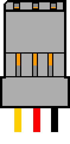
The Servo Plug is a specialized connector designed to interface with servo motors. It typically features three pins: one for power, one for ground, and one for the signal line. This component is widely used in robotics, RC vehicles, and other applications requiring precise motor control. Its compact design and standardized pinout make it a reliable and convenient choice for connecting servo motors to control systems such as microcontrollers or RC receivers.
Explore Projects Built with Servo Plug
 Open Project in Cirkit Designer
 Open Project in Cirkit Designer
 Open Project in Cirkit Designer
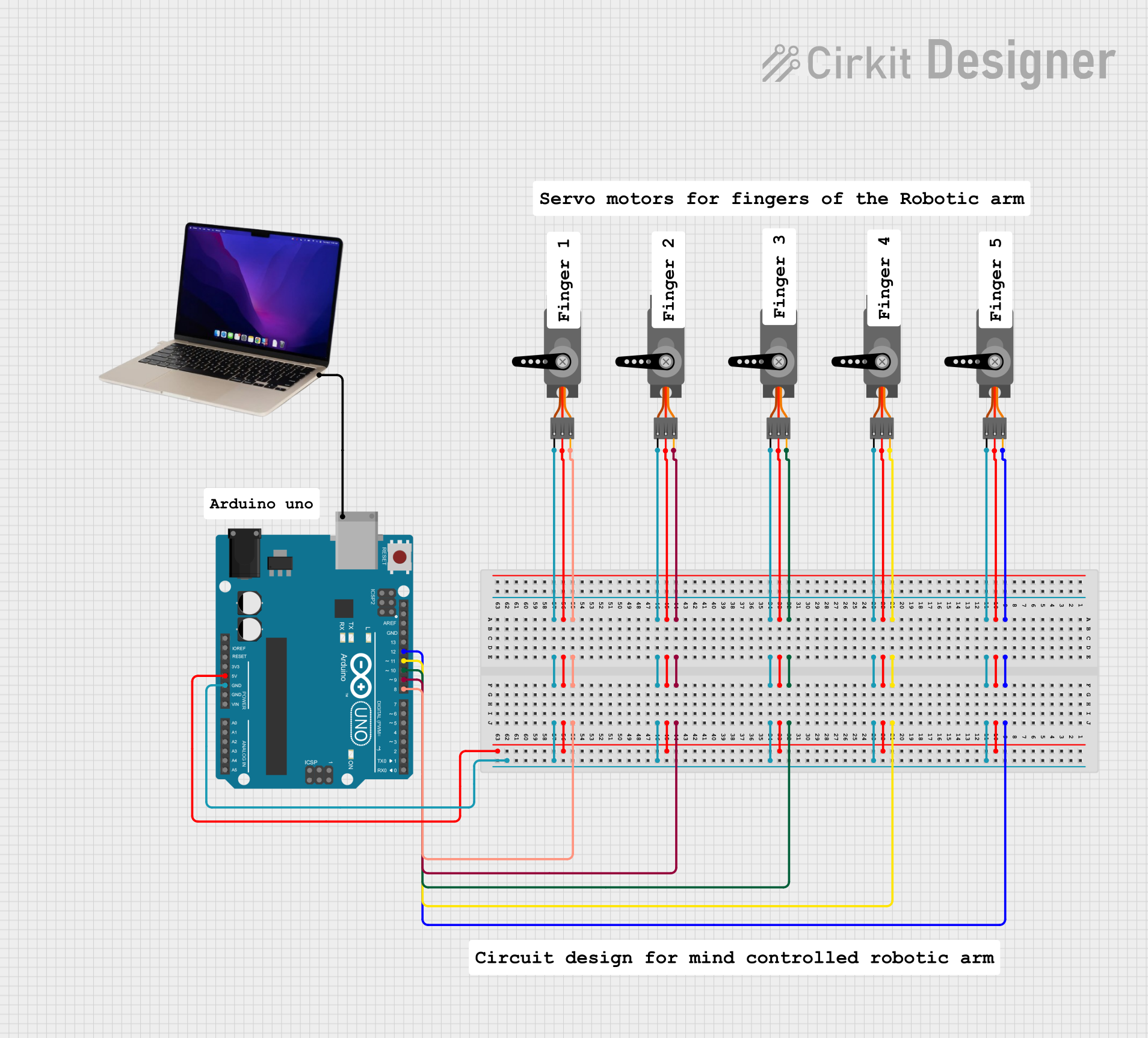 Open Project in Cirkit Designer
Explore Projects Built with Servo Plug
Open Project in Cirkit DesignerOpen Project in Cirkit DesignerOpen Project in Cirkit DesignerOpen Project in Cirkit DesignerCommon Applications
- Robotics and automation systems
- Remote-controlled vehicles (cars, planes, drones, etc.)
- Servo motor testing and prototyping
- DIY electronics projects involving motion control
Technical Specifications
Key Details
- Number of Pins: 3 (Power, Ground, Signal)
- Voltage Range: 4.8V to 6V (typical for most servo motors)
- Current Rating: Up to 3A (depending on the servo motor specifications)
- Connector Type: Male or female, typically with a 2.54mm pitch
- Wire Gauge: 22 AWG to 26 AWG (commonly used with servo plugs)
- Compatibility: Standardized for most hobby-grade servo motors
Pin Configuration and Descriptions
The Servo Plug follows a standard pinout configuration, as shown below:
| Pin Number | Name | Description |
|---|---|---|
| 1 | Signal | PWM signal input for motor control |
| 2 | VCC | Power supply for the servo motor |
| 3 | GND | Ground connection |
Note: The pin order may vary slightly depending on the manufacturer. Always verify the pinout before connecting.
Usage Instructions
Connecting the Servo Plug
- Identify the Pins: Ensure you correctly identify the Signal, VCC, and GND pins on both the servo motor and the Servo Plug.
- Connect to a Microcontroller:
- Attach the Signal pin to a PWM-capable pin on the microcontroller.
- Connect the VCC pin to a 5V or 6V power source (depending on the servo motor's requirements).
- Connect the GND pin to the ground of the microcontroller and power source.
- Secure the Connection: Ensure the plug is firmly seated to avoid loose connections during operation.
Important Considerations
- Power Supply: Use a stable power source capable of supplying sufficient current for the servo motor. Avoid powering the servo directly from the microcontroller's 5V pin if the motor requires high current.
- Signal Voltage: Ensure the PWM signal voltage matches the servo motor's specifications (typically 3.3V or 5V).
- Polarity: Double-check the pin connections to avoid damaging the servo motor or control circuit.
Example: Using a Servo Plug with Arduino UNO
Below is an example of how to control a servo motor using a Servo Plug and an Arduino UNO:
#include <Servo.h> // Include the Servo library

Servo myServo; // Create a Servo object

void setup() {
  myServo.attach(9); // Attach the servo to pin 9 on the Arduino
}

void loop() {
  myServo.write(0); // Move the servo to 0 degrees
  delay(1000);      // Wait for 1 second

  myServo.write(90); // Move the servo to 90 degrees
  delay(1000);       // Wait for 1 second

  myServo.write(180); // Move the servo to 180 degrees
  delay(1000);        // Wait for 1 second
}
Note: Ensure the servo motor is powered by an external power source if it requires more current than the Arduino can provide.
Troubleshooting and FAQs
Common Issues
Servo Motor Not Moving:
- Cause: Incorrect pin connections or insufficient power supply.
- Solution: Verify the pinout and ensure the power source meets the servo motor's requirements.
Erratic or Jittery Movement:
- Cause: Electrical noise or unstable power supply.
- Solution: Use a capacitor across the power and ground pins to filter noise. Ensure the power source is stable.
Overheating Servo Motor:
- Cause: Prolonged operation under high load or incorrect voltage.
- Solution: Check the motor's load and ensure the voltage is within the specified range.
FAQs
Q: Can I use the Servo Plug with a 3.3V microcontroller?
A: Yes, but ensure the servo motor is compatible with a 3.3V PWM signal. If not, use a level shifter to convert the signal to 5V.Q: What is the maximum cable length for a Servo Plug?
A: Cable lengths up to 30cm are generally safe. For longer distances, use thicker wires to minimize voltage drop.Q: Can I connect multiple servos using Servo Plugs?
A: Yes, but ensure the power supply can handle the combined current draw of all servos.
By following this documentation, you can effectively use the Servo Plug in your projects and troubleshoot common issues with ease.